
Removable mother/daughter peripheral card

a peripheral card and mother/daughter technology, applied in the direction of electrical apparatus casing/cabinet/drawer, coupling device connection, instruments, etc., can solve the problems of data loss of ram, large volume, and large volume of mechanical parts, and achieve high precision moving mechanical parts. high precision

Inactive Publication Date: 2006-11-14
SANDISK TECH LLC
View PDF75 Cites 169 Cited by
  • Summary
  • Abstract
  • Description
  • Claims
  • Application Information

AI Technical Summary

Benefits of technology

This configuration results in a cost-effective, flexible, and compact memory system that reduces the need for additional support hardware, allows easy memory capacity adjustments, and enables seamless system updates by replacing only the mother card, thereby enhancing system reliability and portability.

Problems solved by technology

However, RAM is volatile memory; that is, when power to the computer system is disconnected, data stored in RAM is lost.
However, they are relatively slow, bulky and require high precision moving mechanical parts.
Consequently, they are not rugged and are prone to reliability problems, as well as being slower and consuming significant amounts of power.
Disk drives are obstacles in the quest towards greater portability and lower power consumption of computer systems.
However, ROM and PROM cannot be reprogrammed.
The requirement for additional support hardware (e.g. controller) and software (e.g. microcode or firmware and drivers) in these devices poses issues of cost and inflexibility in memory configuration as well as system updating and upgrading.
For example, when Flash EEPROM PC cards are used to replace magnetic floppies or other removable storage, the additional support hardware to implement the control functions may contribute significantly to the cost and other overhead of the product relative to the memory capacity they provide.
Their support hardware and software tend to add cost, overhead and inflexibility to the final products.

Method used


Image

  • Removable mother/daughter peripheral card
  • Removable mother/daughter peripheral card
  • Removable mother/daughter peripheral card

Examples


Embodiment Construction

Semiconductor “Floppies”

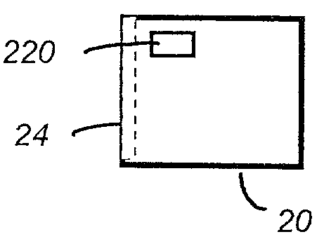
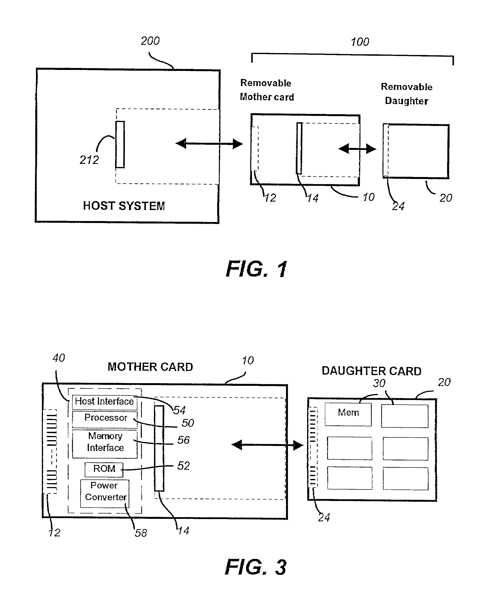
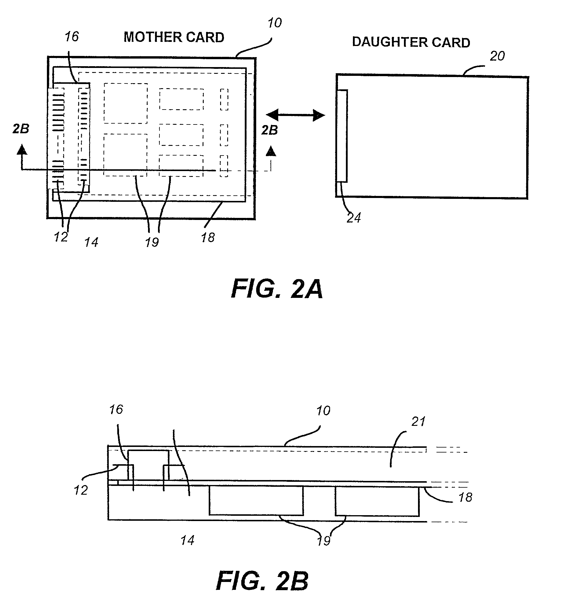
[0050]There are applications where a very low cost memory card is required, for example to replace floppy disks or tape or film. At the same time it is important that the memory card preserve the PCMCIA standard interface to the host system. The present invention is to integrate a memory controller chipset on the memory card in a configuration that minimizes cost and provides maximum flexibility. To reduce the cost of the memory card to meet the cost requirements of a floppy card, it is necessary to either integrate the controller chips with the memory chip, which require greater simplification of the control functionality, or performing most of the control functions by the host CPU which makes this approach host dependent. To solve this problem a lower cost approach is proposed in which the memory card is made up of a mother card and a daughter card.

[0051]FIG. 1 is a schematic representation of the mother / daughter PC card 100 that can be removably coupled ex...


PUM


Abstract

A peripheral card having a Personal Computer (“PC”) card form factor and removably coupled externally to a host system is further partitioned into a mother card portion and a daughter card portion. The daughter card is removably coupled to the mother card. In the preferred embodiment, a low cost flash “floppy” is accomplished with the daughter card containing only flash EEPROM chips and being controlled by a memory controller residing on the mother card. Other aspects of the invention includes a comprehensive controller on the mother card able to control a predefined set of peripherals on daughter cards connectable to the mother card; relocation of some host resident hardware to the mother card to allow for a minimal host system; a mother card that can accommodate multiple daughter cards; daughter cards that also operates directly with hosts having embedded controllers; daughter cards carrying encoded data and information for decoding it; and daughter cards with security features.

Description

[0001]This is a continuation of application Ser. No. 09 / 887,197, filed Jun. 21, 2001, now U.S. Pat. No. 6,381,662, which is a continuation of application Ser. No. 09 / 241,222, filed Feb. 1, 1999, now U.S. Pat. No. 6,266,724, which is a continuation of application Ser. No. 08 / 781,539, filed Jan. 9, 1997, now U.S. Pat. No. 5,887,145, which is a continuation of application Ser. No. 08 / 462,642, filed Jun. 5, 1995, now abandoned, which is a continuation of application Ser. No. 08 / 398,856, filed Mar. 6, 1995, now abandoned, which is a continuation of application Ser. No. 08 / 151,292 filed Nov. 12, 1993, now abandoned, which is a continuation-in-part of application Ser. No. 08 / 115,428 filed Sep. 1, 1993, now abandoned. U.S. Pat. No. 5,887,145 is hereby incorporated herein by this reference.BACKGROUND OF THE INVENTION[0002]This invention relates generally to host computer systems and peripherals. More specifically, the peripherals have a Personal Computer (“PC”) card form factor, the card bei...

Claims


Application Information

Patent Timeline
Patent Type & Authority Patents(United States)
IPC IPC(8): G06F12/14G06F12/00G06F13/00G06F3/00G06F13/40H05K5/02
CPCG06F13/4068G06K19/07741H05K5/0265H05K5/0282
Inventor HARARI, ELIYAHOUGUTERMAN, DANIEL C.WALLACE, ROBERT F.
Owner SANDISK TECH LLC
Learn More