Constant volume combustor

a combustor and constant volume technology, applied in the direction of machines/engines, jet propulsion plants, hot gas positive displacement engine plants, etc., can solve the problems of unrealized potential for wave rotor and pulse detonation technologies, unsteady flow produced by detonation, and multiplicity of mechanical and aerodynamic based challenges

Inactive Publication Date: 2006-11-21
ROLLS ROYCE NORTH AMERICAN TECH
View PDF23 Cites 30 Cited by
  • Summary
  • Abstract
  • Description
  • Claims
  • Application Information

AI Technical Summary

Problems solved by technology

One of the next big challenges in the area of commercial and military flight is the improvement in fuel economy as flight speeds increase well into the supersonic range.
However, a significant drawback with pulse detonation has been the unsteady flow produced due to the sequencing of detonations to produce thrust or combustion.
This unsteady flow is envisioned to result in a multiplicity of mechanical and aerodynamic based challenges.
However, until the present invention the potential for wave rotor and pule detonation technologies has not been realized.

Method used


Image

  • Constant volume combustor
  • Constant volume combustor
  • Constant volume combustor

Examples


Embodiment Construction

[0036]For the purpose of promoting an understanding of the principles of the invention, reference will now be made to the embodiments illustrated in the drawings and specific language will be used to describe the same. It will nevertheless be understood that no limitation of the scope of the invention is thereby intended. Any alterations and further modifications in the described embodiments, and any further applications of the principles of the invention as described herein are contemplated as would normally occur to one skilled in the art to which the invention relates.

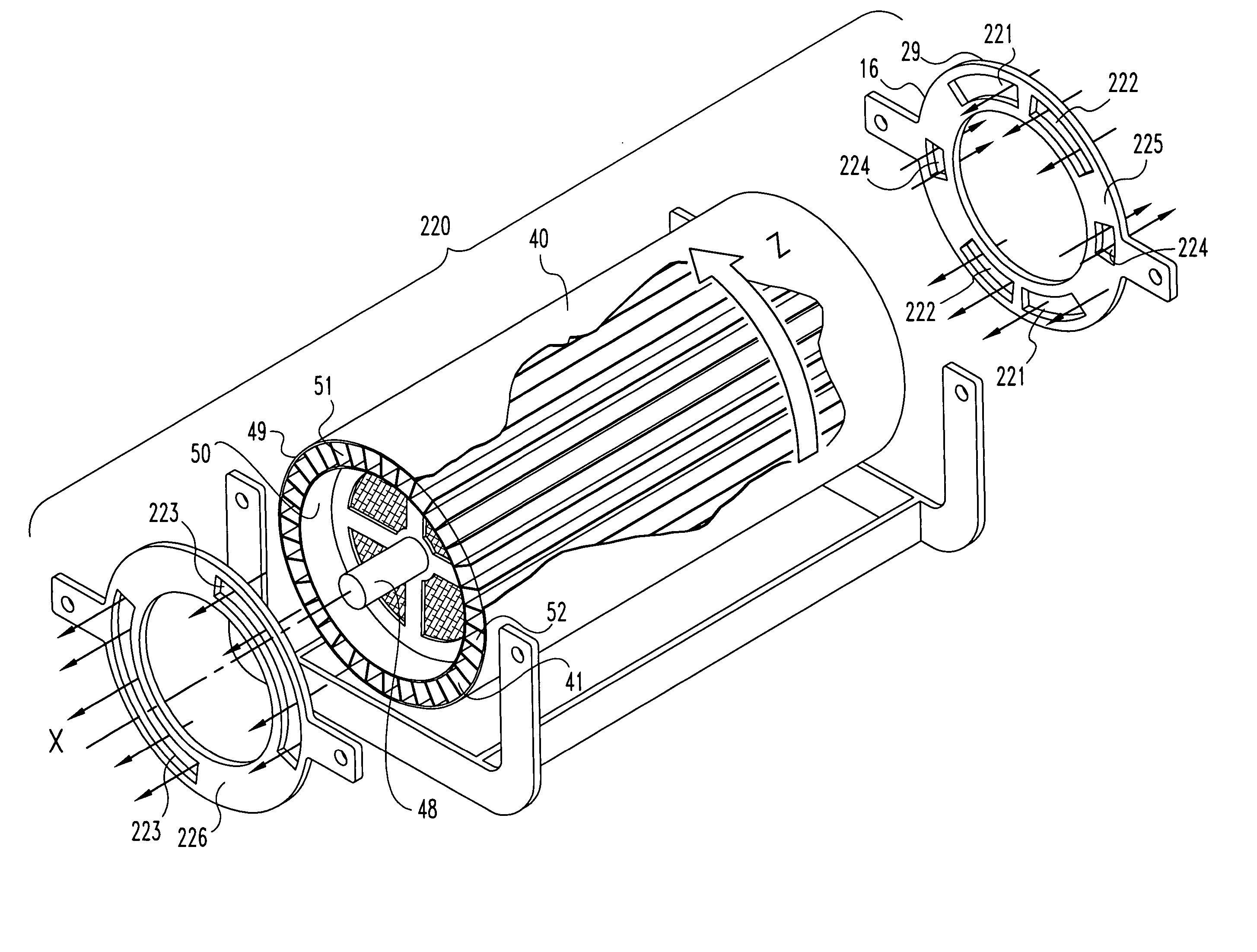
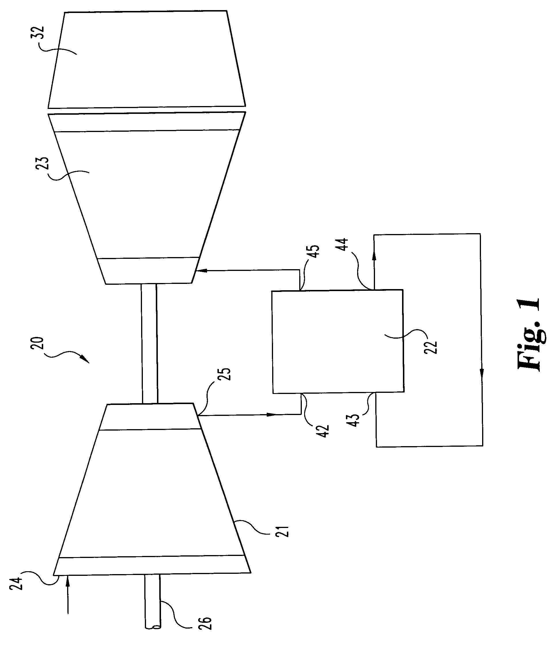
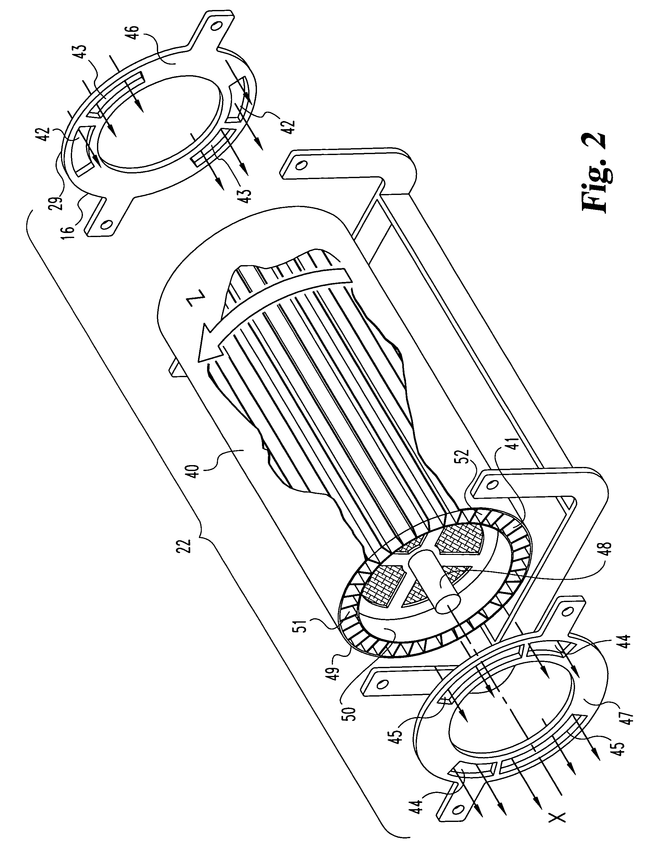
[0037]With reference to FIG. 1, there is illustrated a schematic representation of a propulsion system 20 which includes a compressor 21, a pulsed combustion wave rotor 22, a turbine 23, a nozzle 32, and an output power shaft 26. The compressor 21 delivers a precompressed working fluid to the pulsed combustion wave rotor device 22. Wave rotor device 22 has occurring within its passageways the combustion of a fuel an...


PUM


Abstract

A pressure wave apparatus utilizing the principles of pulsed detonation and wave rotor technologies. The apparatus includes inlet and outlet ports that interface with a plurality of fluid flow passageways on a rotor. A buffer gas is routed through some of the inlet and outlet ports and into and out of the plurality of fluid flow passageways. One of the inlet ports is a buffer gas inlet port that when placed in registry with a fluid flow passageway allows the flow of buffer gas into the respective passageway. Fuel is delivered into the buffer gas proximate the buffer gas inlet port so that only a portion of the buffer gas inlet port receives any fuel.

Description

CROSS REFERENCE TO RELATED APPLICATIONS[0001]The present application claims the benefit of U.S. Provisional Application No. 60 / 393,727 filed Jul. 3, 2002, and incorporated herein by reference.[0002]The present application was made under contract MDA972-01-2-0014 by DARPA, and DARPA may have certain rights herein.BACKGROUND OF THE INVENTION[0003]The present invention relates generally to a constant volume combustion device including detonative combustion. More specifically, one form of the present invention is a combustion unit having a high pressure rise, a near time-steady inflow and outflow, while being self cooled. The constant volume combustor has properties of pulse detonation and wave rotor technologies. Although the present invention was developed for use as a combustor within a gas turbine engine, certain applications may be outside of this field.[0004]One of the next big challenges in the area of commercial and military flight is the improvement in fuel economy as flight sp...

Claims


Application Information

Patent Timeline
Patent Type & Authority Patents(United States)
IPC IPC(8): F02K5/02F02K7/00F02C3/02F02C5/12
CPCF02C3/02F02C5/12
Inventor SNYDER, PHILIP H.EMMERSON, CALVIN W.
Owner ROLLS ROYCE NORTH AMERICAN TECH
Why Eureka
Try Eureka