Optical ink level detecting arrangements for ink cartridges

Inactive Publication Date: 2006-11-21
NU KOTE INT
View PDF7 Cites 11 Cited by
  • Summary
  • Abstract
  • Description
  • Claims
  • Application Information

AI Technical Summary

Benefits of technology

[0003]In accordance with the present invention, improvements are provided with respect to optical prism arrangements for ink jet cartridges by which the foregoing and other disadvantages of cartridges heretofore available are minimized or overcome. More particularly in this respect, and in accordance with one aspect of the invention, multiple, independent prism segments are provided in an ink cartridge which allows one cartridge configuration to be used in single or multi-printhead printers. The interface of each of the prisms is in a corresponding plane transverse to the direction between the front and rear ends of the cartridge, whereby th

Problems solved by technology

Furthermore, optical prisms provided in cartridges heretofore available are formed integral with the bottom wall of the cartridge

Method used


Image

  • Optical ink level detecting arrangements for ink cartridges
  • Optical ink level detecting arrangements for ink cartridges
  • Optical ink level detecting arrangements for ink cartridges

Examples


Example

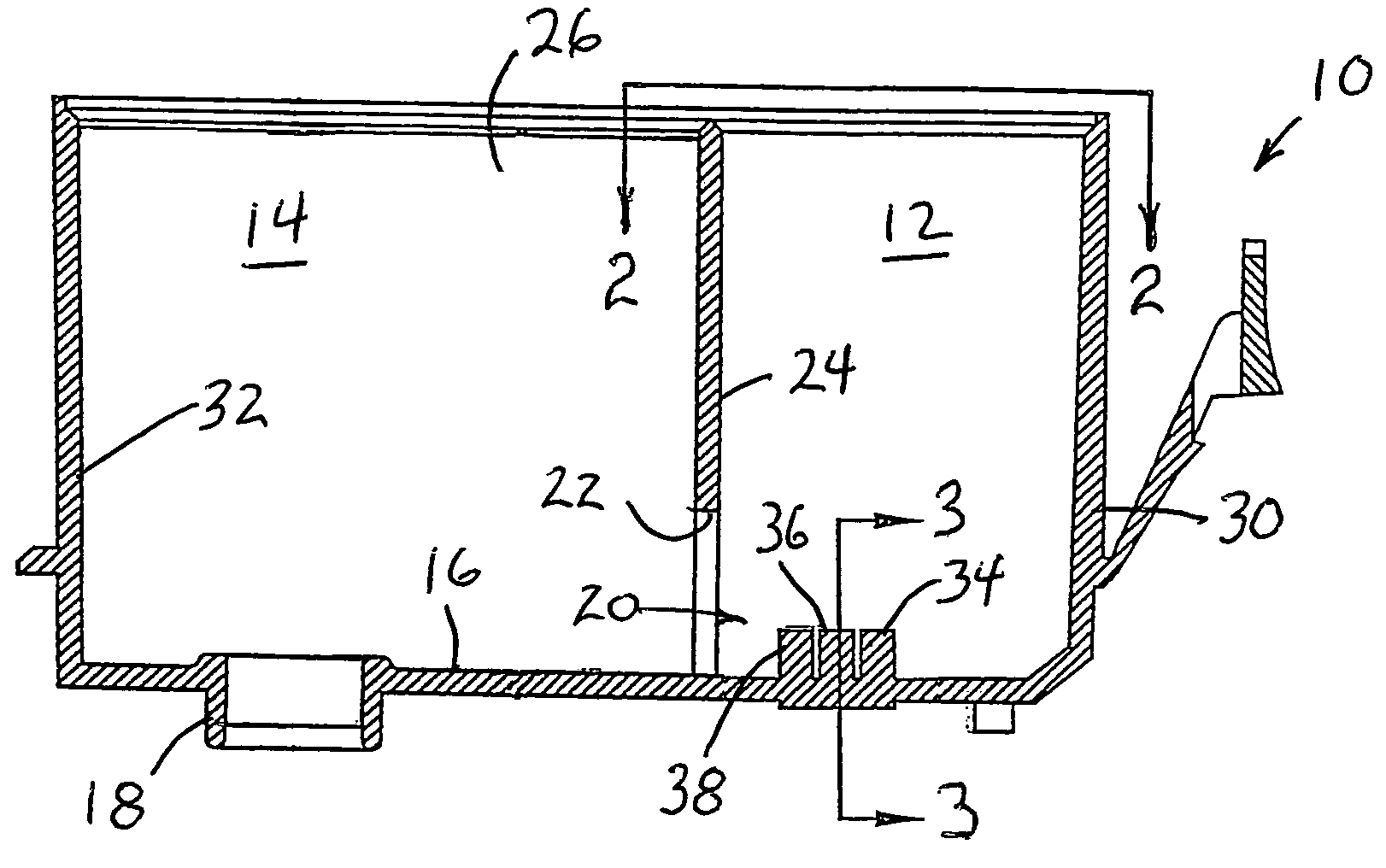
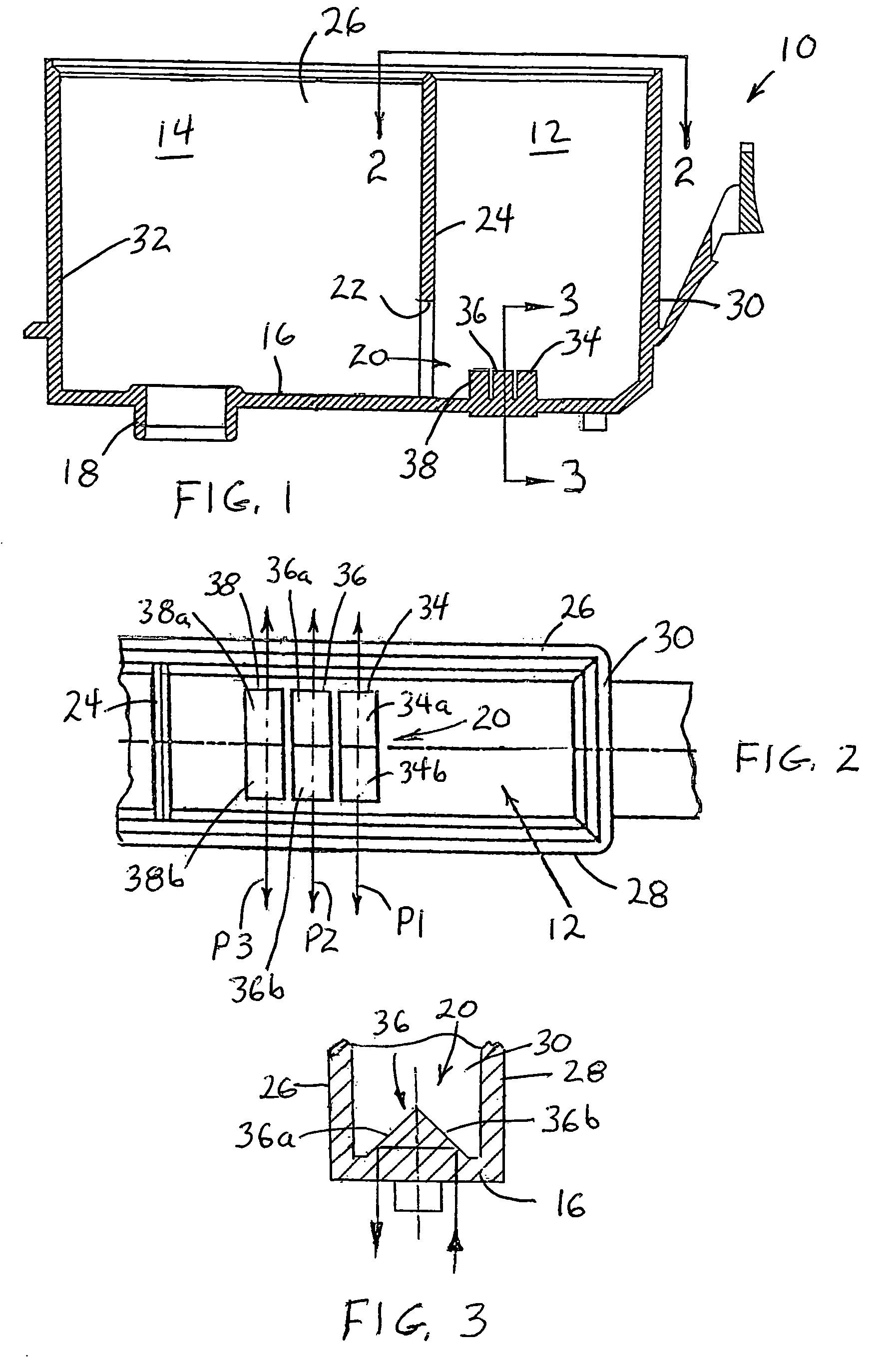
[0016]Referring now in greater detail to the drawings, wherein the showings are for the purpose of illustrating preferred embodiments of the invention only and not for the purpose of limiting the invention, FIGS. 1–3 illustrate an ink cartridge 10 having ink chambers 12 and 14 and a bottom wall 16 having an ink outlet 18 from chamber 14 and an optical prism unit 20 in chamber 12. While not shown, chamber 14 is generally provided with a block of porous ink absorbing material, and chamber 12 generally receives free ink which is progressively fed to the ink absorbing material in chamber 14 through a window or opening 22 in a partition wall 24 which divides the interior of the cartridge into the two chambers. The cartridge further includes side walls 26 and 28 and front and rear walls 30 and 32, respectively.

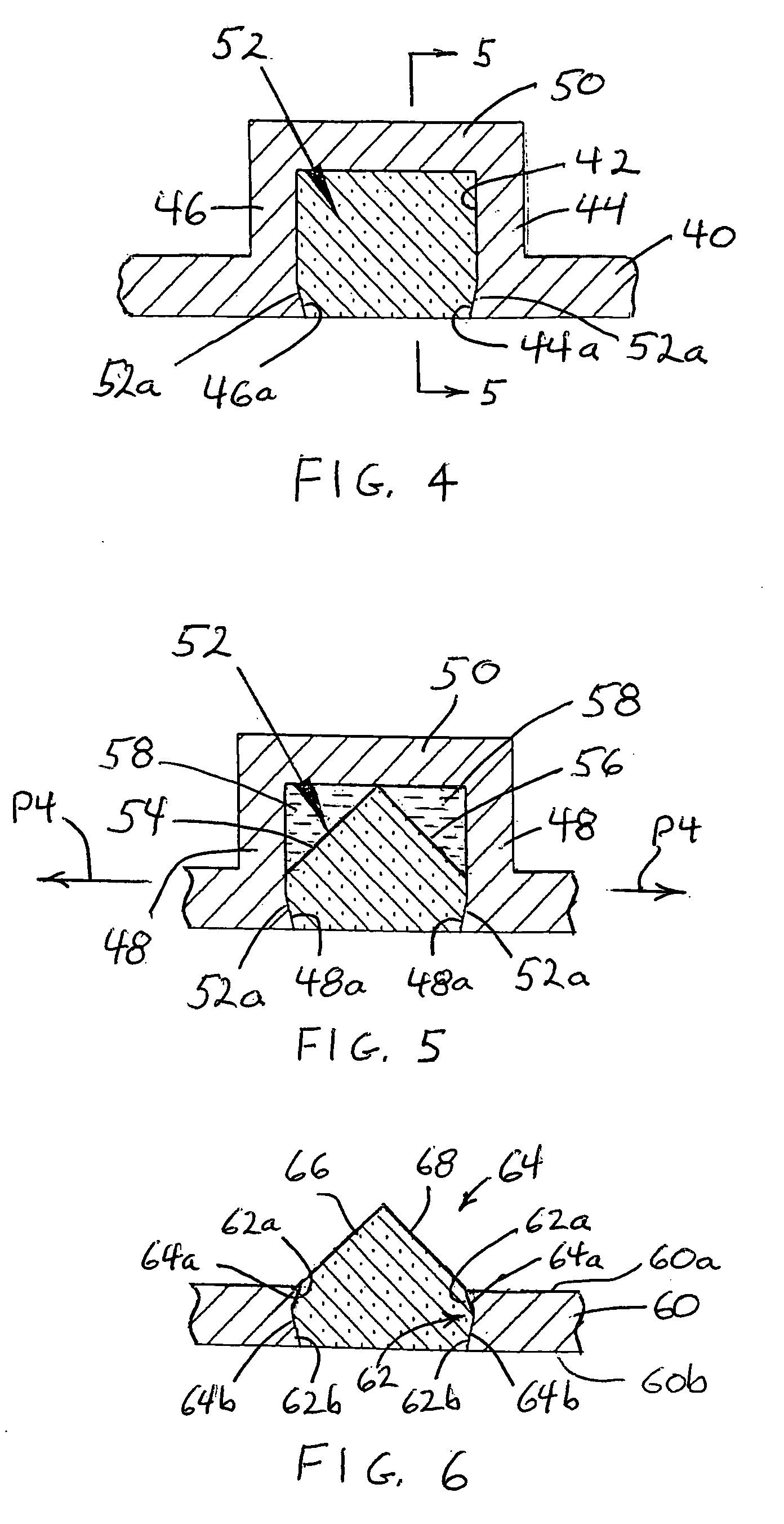
[0017]In accordance with this embodiment, at least the portion of bottom wall 16 supporting the optical prism is of light transmitting material, and optical prism unit 20 comprises ...


PUM


Abstract

An ink container shell for an ink jet cartridge has an ink chamber provided with an optical ink detection device in the form of a single or multi-segment prism having interface surfaces for reflecting light in a scan plane from a first to a second exterior area relative to the container shell when an ink level in the chamber recedes to a given level. The multi-segment prism provides for scanning a cartridge in different scanning planes. Either a single prism or the multi-segment prism can be separate from the cartridge and interengaged therewith by a snap-fit.

Description

BACKGROUND OF THE INVENTION[0001]It is of course known to provide ink cartridges for printers with arrangements for optically detecting the level of ink in a chamber or chambers of an ink cartridge. Generally, the optical system includes an optical ink detecting section, such as a prism, in an ink chamber of a cartridge and which is immersed in the ink when the latter is in the chamber above a certain level, and the ink level is read by a light emitting optical unit comprising a light emission device and a photo receptor outside the cartridge. The interface of the optical detecting section extends transverse to the plane of scanning as defined by the light path between the emitter and receptor. If, for example, the scanning takes place in a printer, and the cartridge moves transverse to the direction between the front and rear ends thereof, the plane of the light path between the emitter and receptor is likewise transverse to the direction between the front and rear ends of the cart...

Claims


Application Information

Patent Timeline
IPC IPC(8): B41J2/045
CPCB41J2/17566
Inventor ANDERSEN, STEPHEN A.LENGYEL, DENNIS M.
Owner NU KOTE INT
Why Eureka
Try Eureka