Sensor-holding lid for a wheel hub bearing

a technology of hub bearing and sensor, which is applied in the direction of bearings, speed/acceleration/shock instrument details, devices using electric/magnetic means, etc., can solve the problems of affecting the bearing, stagnation, freezing,

Inactive Publication Date: 2006-11-21
SKF IND SPA
View PDF11 Cites 5 Cited by
  • Summary
  • Abstract
  • Description
  • Claims
  • Application Information

AI Technical Summary

Benefits of technology

[0006]The aim of the present invention is to produce a sensor-holding lid for a wheel hub bearing, which will permit the disadvantages described above to be overcome in a simple cost-effective manner.

Problems solved by technology

The waterproof shield is, obviously, an additional element which increases the production costs of he wheel bearing, as well as increasing the axial dimensions, and, furthermore, does not completely protect the bearing from any eventual breakage caused by the liquid which, despite the presence of the draining channels, can still stagnate and freeze at low temperatures.

Method used


Image

  • Sensor-holding lid for a wheel hub bearing
  • Sensor-holding lid for a wheel hub bearing
  • Sensor-holding lid for a wheel hub bearing

Examples


Embodiment Construction

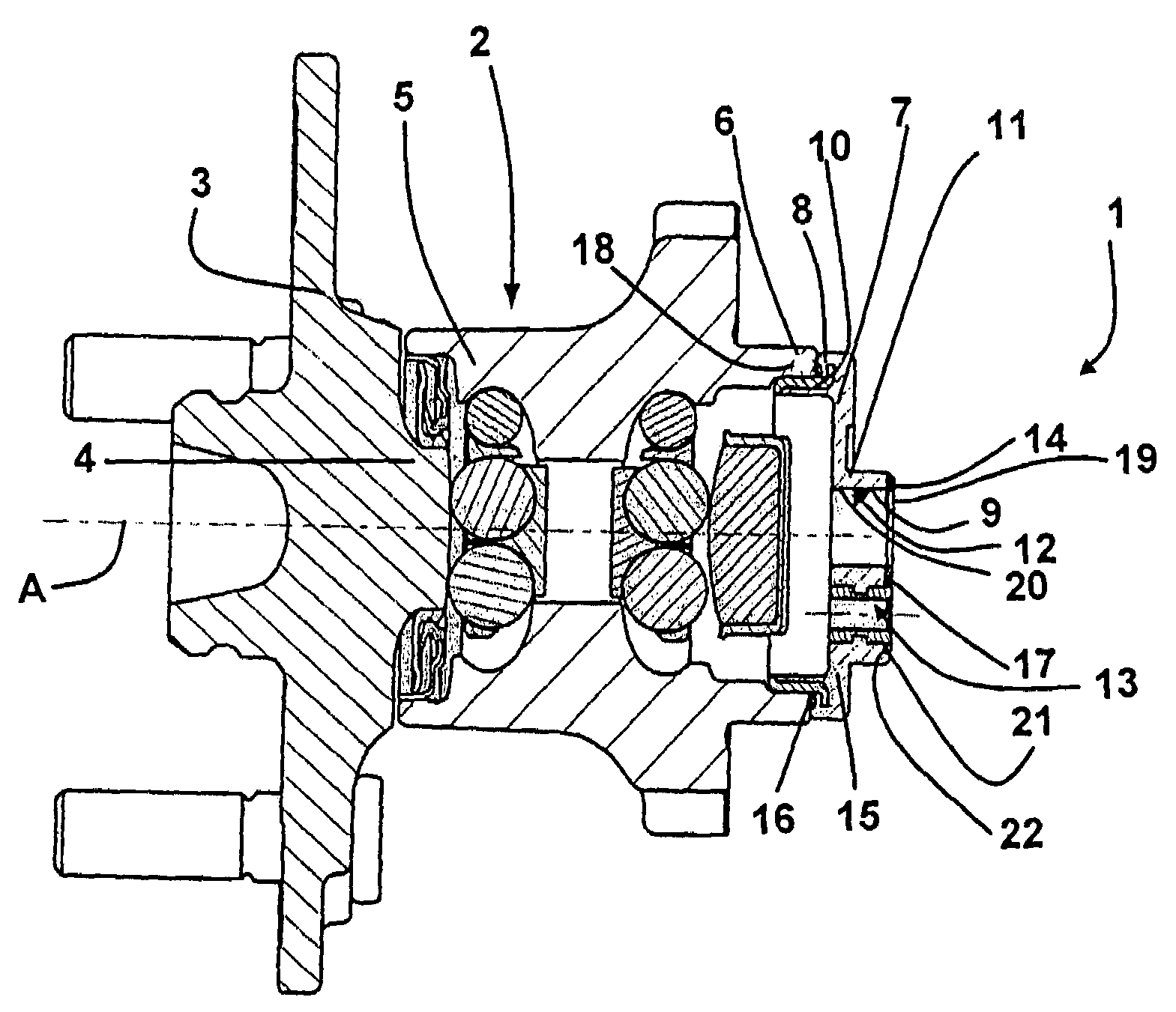
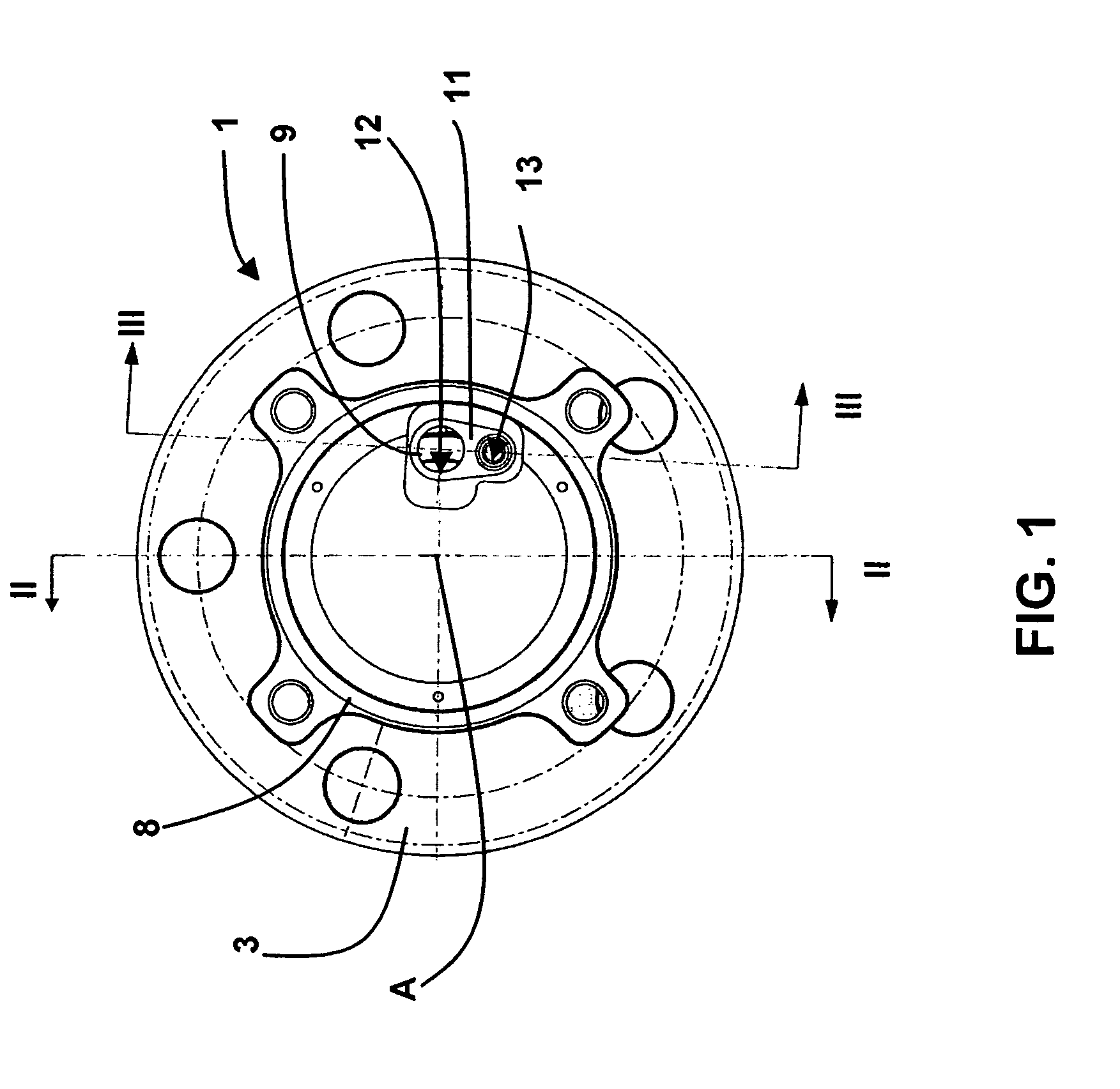
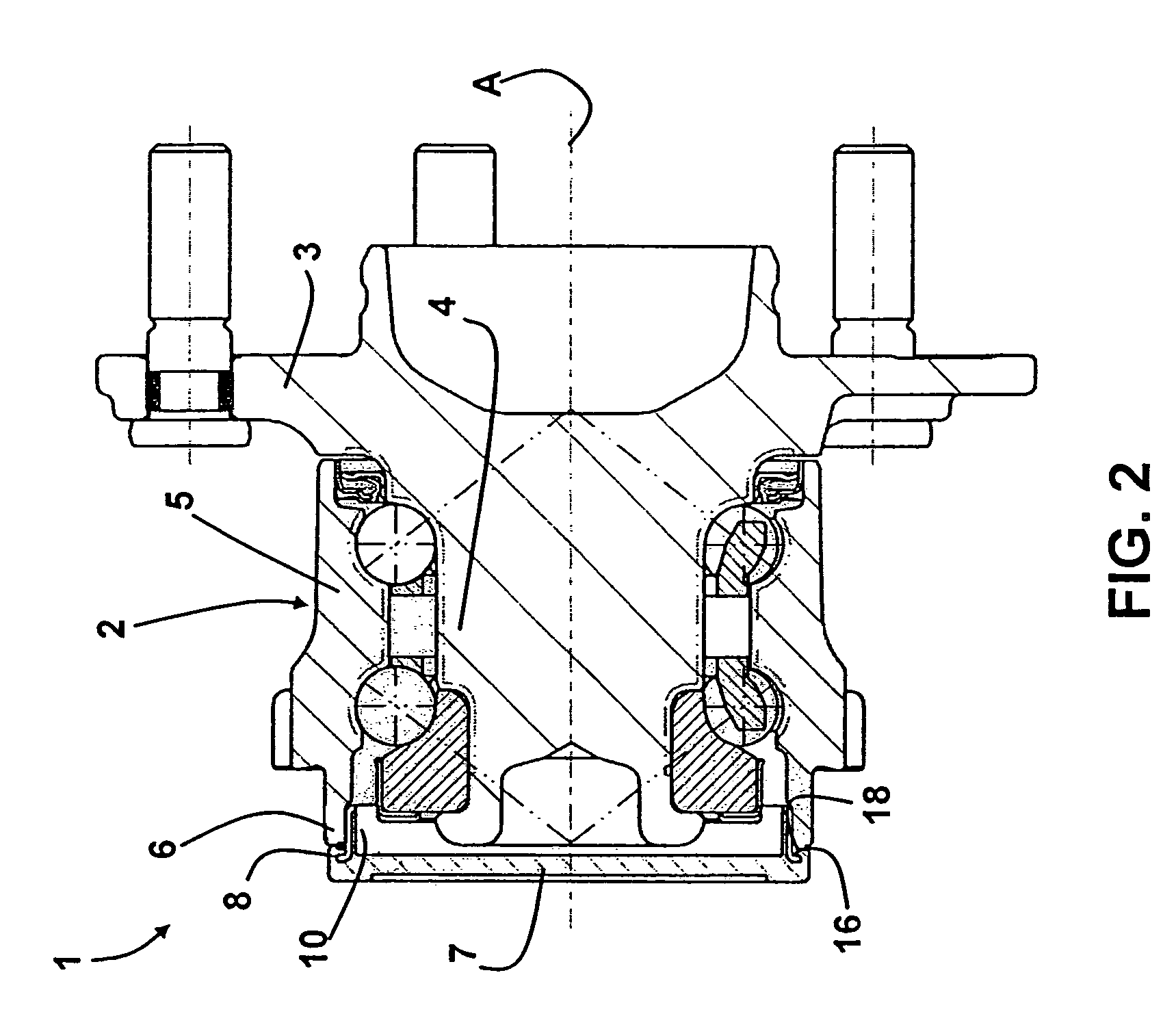
[0010]The invention will now be described with reference to the attached drawings, which illustrate a non-limiting form of embodiment of the present invention. With reference to FIGS. 1 and 2, the number 1 refers to a sensor-holding lid, in its entirety, for a bearing 2 of a wheel hub 3.

[0011]The bearing 2 comprises an inner race 4 which turns around a rotation axis A and which is an integral part of the wheel hub 3, and a fixed outer race 5, which is co-axial to the inner race 4, and which is provided with an annular border 6.

[0012]The lid 1 is mounted onto the outer race 5, and it comprises a base wall 7, which is arranged transverse to the A axis, and which is externally delimited by an annular peripheral border 8 which is arranged directly facing the border 6. The lid 1 also comprises a seat 9 which is integral to the base wall 7 for housing a sensor (taken note of, but not illustrated) and a cylindrical wall 10, which is transverse to the wall 7, and which is arranged radially ...


PUM


Abstract

Sensor-holding lid for a wheel hub bearing, the lid presenting a base wall which is externally delimited by a peripheral border, an axial ledge which is integral to the wall and which is provided with a passing hold for housing the sensor, and a cylindrical wall which is transverse to the base wall and which is arranged radially inside the peripheral wall in order to be fixed onto an external border of the bearing; at least two annular static sealing elements which are made of rubber and which are co-molded, respectively, into the peripheral border on the outside of the cylindrical wall and inside an entry border of the passing hole.

Description

CROSS-REFERENCE TO RELATED APPLICATIONS[0001]This application claims priority to Italian patent number 2002A000042.FIELD OF INVENTION[0002]The present invention refers to a sensor-holding lid for a wheel hub bearing.BACKGROUND[0003]In general, sensor-holding lids of a well-known type comprise a base wall which is externally delimited by a circular border, an axial ledge which is integral to the wall and which is provided with a passing hole for housing the sensor, and a cylindrical wall which is provided with a passing hole for housing he sensor, and a cylindrical wall which is transverse to the base wall and which is arranged radially inside the circular border in order to be fixed onto an annular border to the rolling race outside the bearing.[0004]Due to the extremely poor environmental conditions in which the bearing has to operate and which result in the infiltration of liquid via the hole for the sensor into the inside of the bearing itself, the latter is further provided with...

Claims


Application Information

Patent Timeline
Patent Type & Authority Patents(United States)
IPC IPC(8): F16C32/00B60B27/00F16C33/72G01P1/02G01P3/44
CPCB60B27/00F16C33/723F16C41/007G01P1/026G01P3/443F16C19/186F16C2326/02
Inventor VIGNOTTO, ANGELOMARIVO, MASSIMO
Owner SKF IND SPA
Why Eureka
Try Eureka