Transporting apparatus with position detection sensor

a technology of position detection and transporting equipment, which is applied in the direction of computer control, program control, instruments, etc., can solve the problem of greater likelihood of problems in the use life of cables, and achieve the effect of improving the system li

Active Publication Date: 2006-11-21
DAIFUKU CO LTD
View PDF17 Cites 19 Cited by
  • Summary
  • Abstract
  • Description
  • Claims
  • Application Information

AI Technical Summary

Benefits of technology

[0006]It is an object of the present invention to provide a transporting apparatus that is capable of detecting changes in the article loading state while achieving an improvement in system life, even when detection information is obtained by a cable connected to the article loading state detection sensor.

Problems solved by technology

In this case, the cable is bent or stretched because each time the article loading platform is advanced or retreated the article loading state detection sensor moves together with the article loading platform, resulting in a greater likelihood that problems will arise in the usage life of the cable.

Method used


Image

  • Transporting apparatus with position detection sensor
  • Transporting apparatus with position detection sensor
  • Transporting apparatus with position detection sensor

Examples


first embodiment

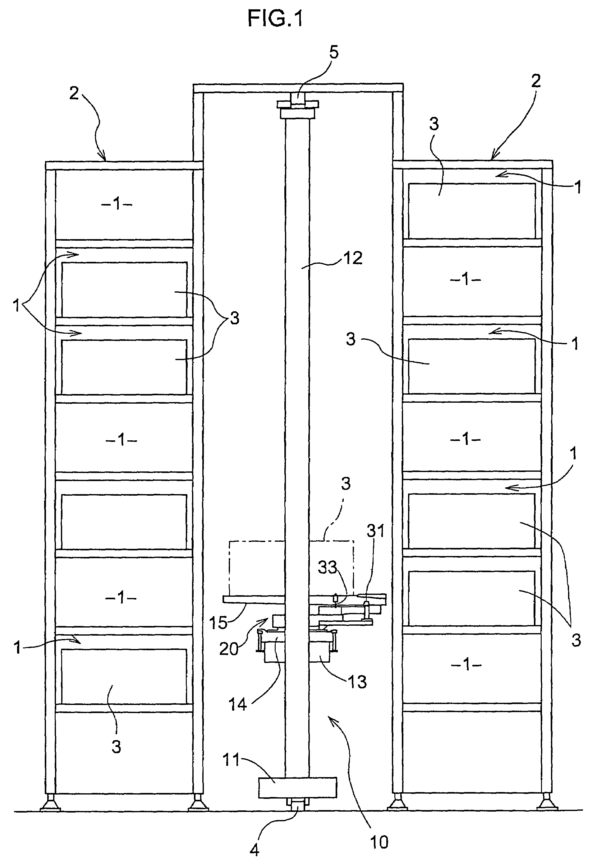
[0025]As shown in FIG. 1, an automated warehouse has a pair of storage shelves 2, and each storage shelf 2 has a plurality of article storage portions 1 provided lined up horizontally and vertically. The pair of storage shelves 2 are arranged side by side on the floor such that their front face sides face each other with a predetermined space between them. A transporting apparatus 10 is provided between the storage shelves 2.

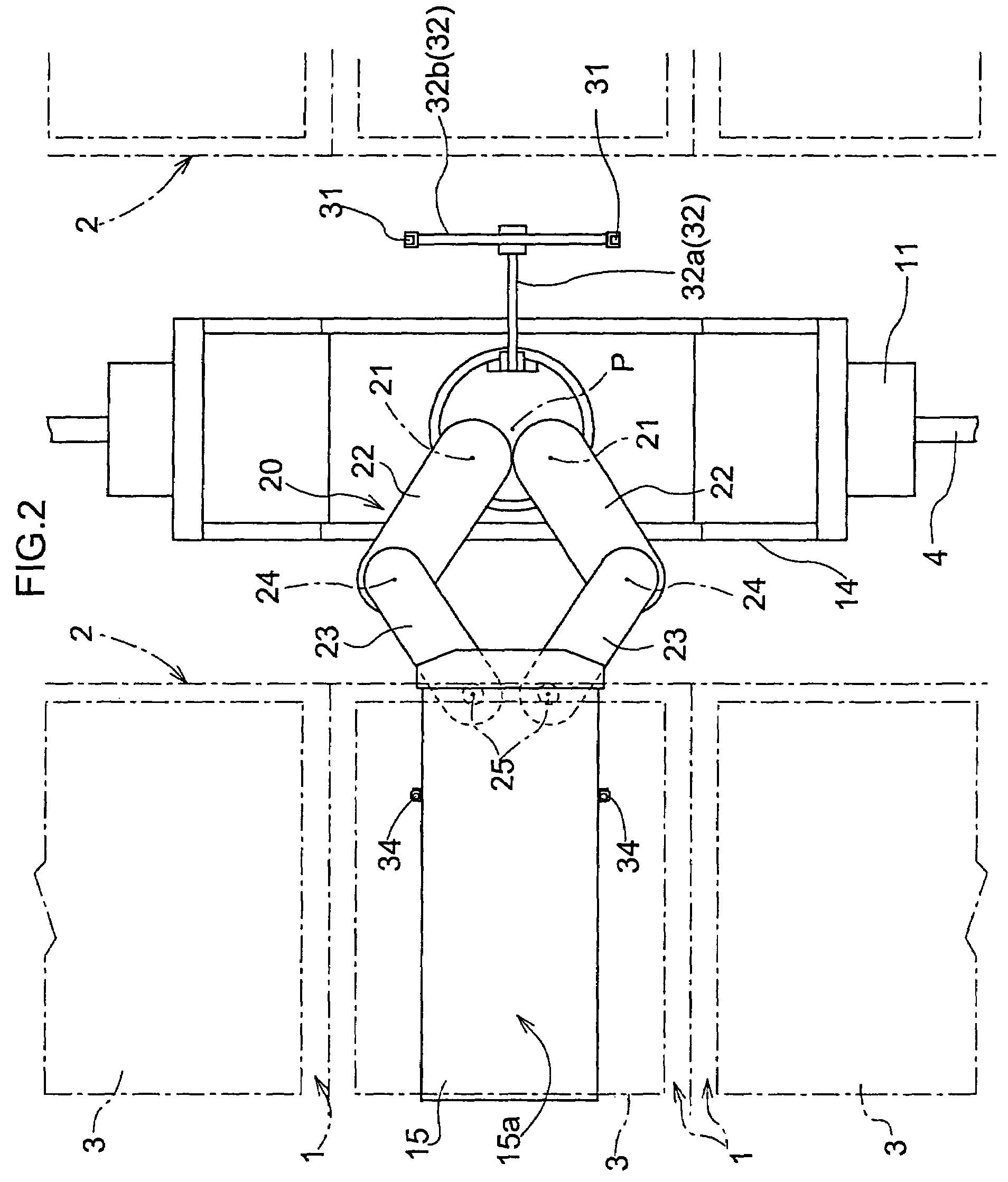
[0026]The transporting apparatus 10 is operated automatically based on an operation command, and moves between the storage shelves 1 and an article delivery portion (not shown) positioned to the side of the storage shelves 2. The transporting apparatus 10 is capable of removing an article that has been carried, stored in a receptacle 3, to the article delivery portion from the article delivery portion with the article still being stored in the receptacle, transporting it to an article storage portion 1 of a predetermined storage shelf 2, and storing it in the ar...

second embodiment

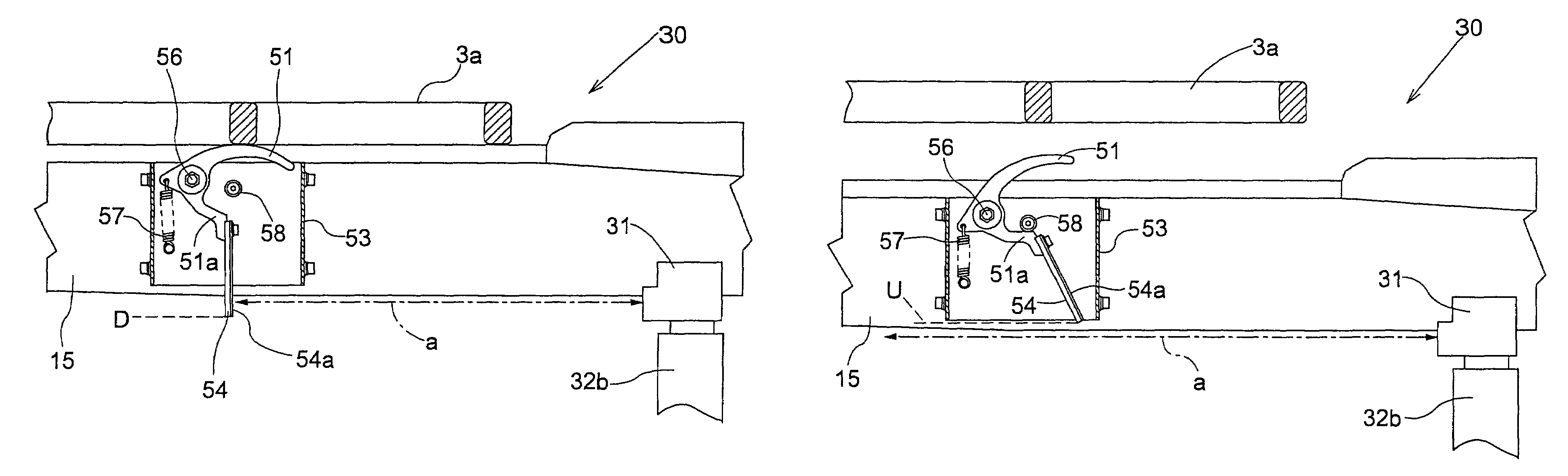
[0046]A second embodiment is described below, and because this second embodiment is a separate embodiment of the structure of the operating member 34 according to the first embodiment, the operating member 34 is described in detail but other structural elements are the same as in the first embodiment and thus a detailed explanation thereof is omitted.

[0047]As shown in FIG. 10, the loaded article loaded on the article loading platform 15 is an article 3a whose lower surface is a grating. As shown in FIG. 12, a pair of operating members 51 are provided in the shape of a lever such that by loading the article 3a onto the article loading platform 15 in a predetermined loading position or loading orientation the loaded article 3a depresses the pair of operating members 51. In FIG. 10 only the lower surface portion of the article 3a is shown.

[0048]As shown in FIG. 11, when viewed in plan view, the operating members 51 are elongate plates (that is to say, elongate members) that run along t...


PUM


Abstract

A transporting apparatus is provided with a moving platform capable of moving vertically, an article loading platform that can be moved horizontally with respect to the moving platform, a contactless sensor provided on the moving platform, a detected member that is provided on the article loading platform, whose position can be altered between an position detected and a position not detected by the contactless sensor, and an operating member operatively linked to the detected member. The operating member can come into contact with an article loaded on the article loading platform, and changes the position of the detected member between the detected position and the non-detected position. Due to this configuration, it is possible to provide an article position sensor between the article loading platform and the moving platform without using wires, which are deteriorated due to the relative movement between the article loading platform and the moving platform.

Description

BACKGROUND OF THE INVENTION[0001]The present invention relates to transporting apparatuses used in automated warehouses, and more specifically to transporting apparatuses in which a loading platform for transporting articles is provided that is capable of horizontally advancing and retreating to a moving platform that is raised and lowered.[0002]Such a transporting apparatus is disclosed for example in JP 2000-219498A (paragraphs [0017] and [0018], FIGS. 1 and 2), and is an apparatus for transporting articles set on an article loading platform. This apparatus has a vehicle that moves horizontally near the ground, a support column fixed to the vehicle and extending vertically, a raising and lowering stand that moves vertically along this support column, and an article loading platform on which articles are loaded and which can move between a home position and an extended position with respect to the raising and lowering stand. In the position opposite a desired article storage portio...

Claims


Application Information

Patent Timeline
Patent Type & Authority Patents(United States)
IPC IPC(8): B66F9/24B65G1/04
CPCB65G1/0435B65G1/04B65G2203/042
Inventor UEDA, KATSUHIKO
Owner DAIFUKU CO LTD
Why Eureka
Try Eureka