
Knockdown labyrinth framework

a technology of labyrinth and knockdown, applied in the field of tubular framework, can solve the problems of difficult assembly or disassembly, and achieve the effect of easy setting up and knocking down

Inactive Publication Date: 2006-11-21
SAVAGE PIERRE
View PDF10 Cites 6 Cited by
  • Summary
  • Abstract
  • Description
  • Claims
  • Application Information

AI Technical Summary

Benefits of technology

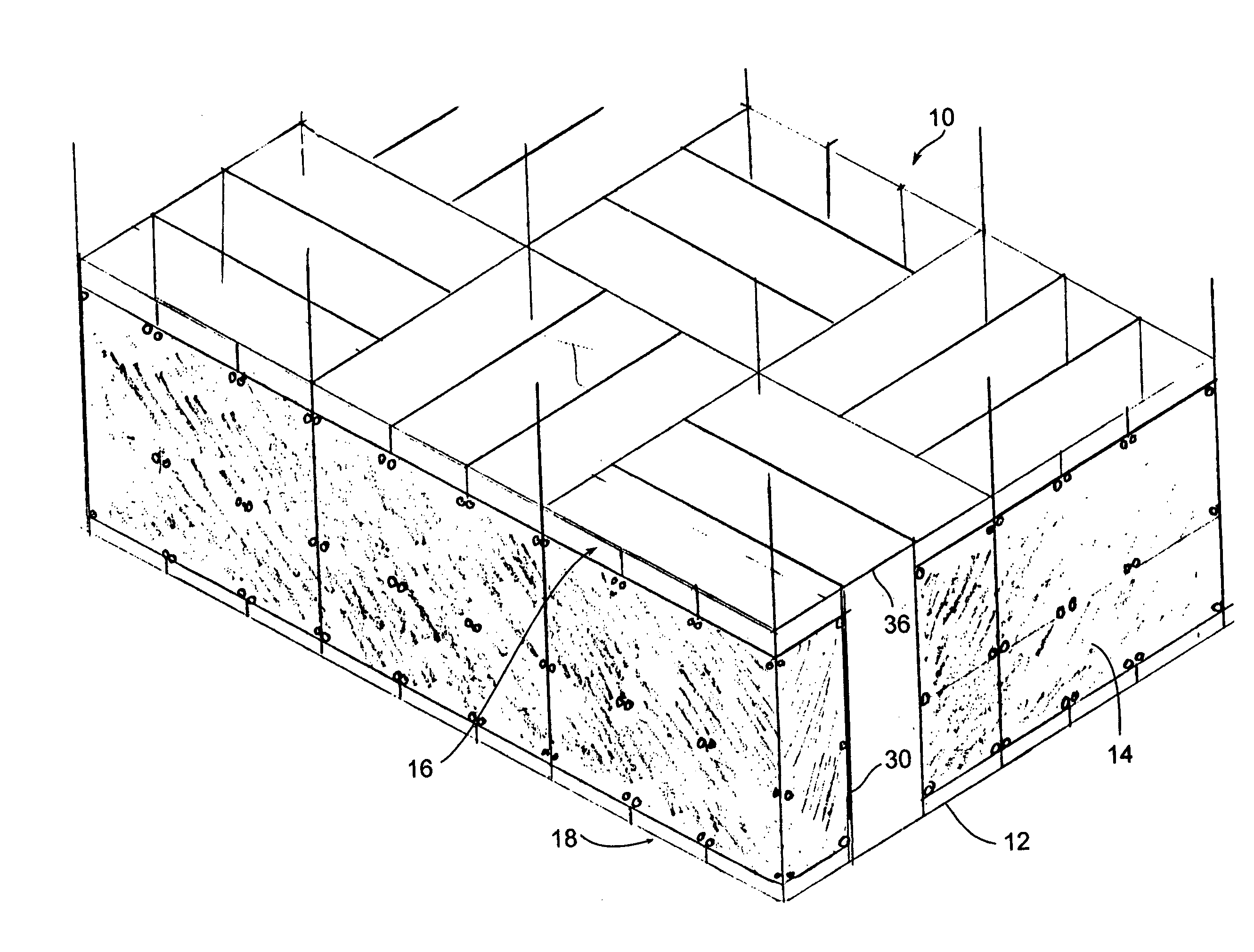
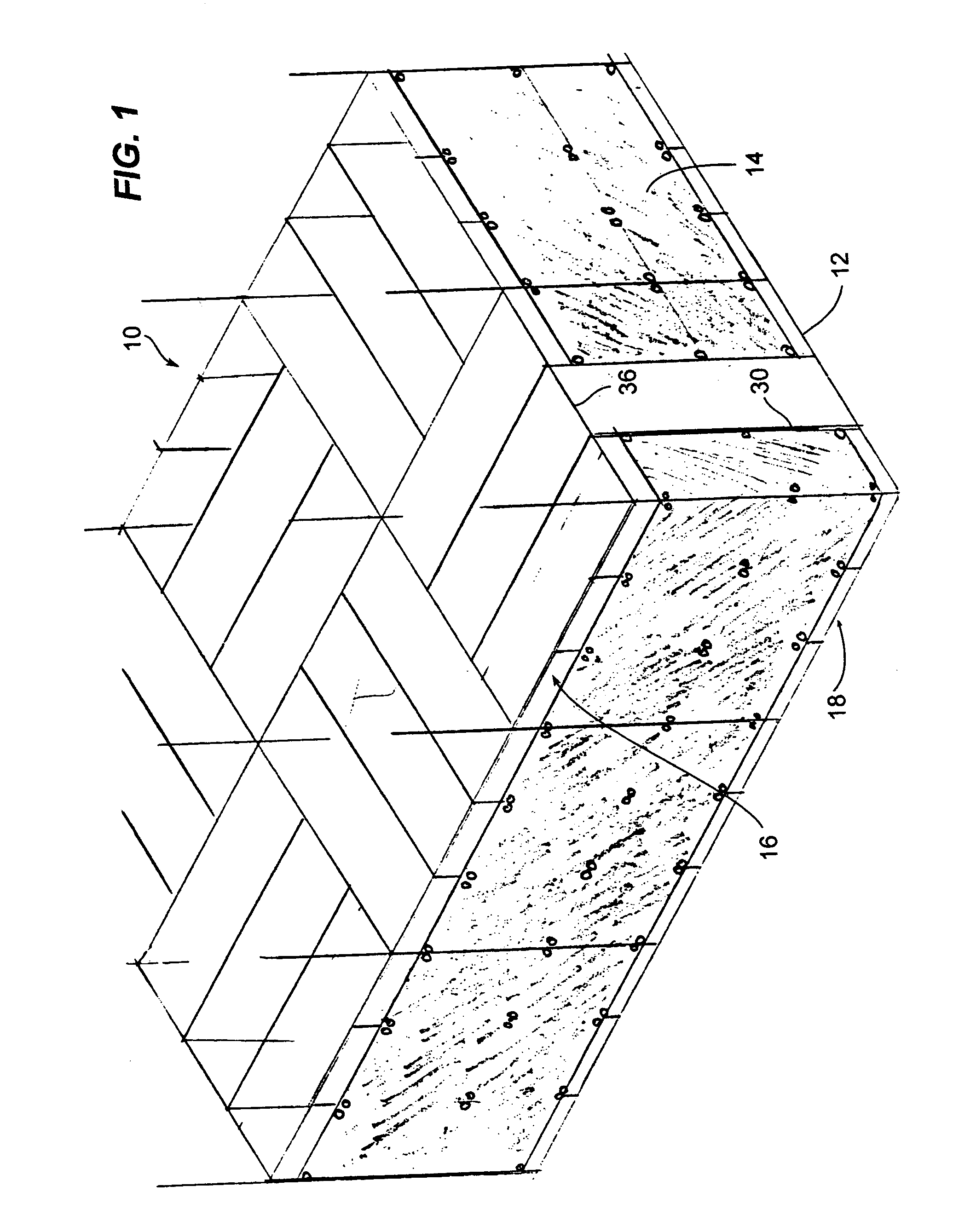
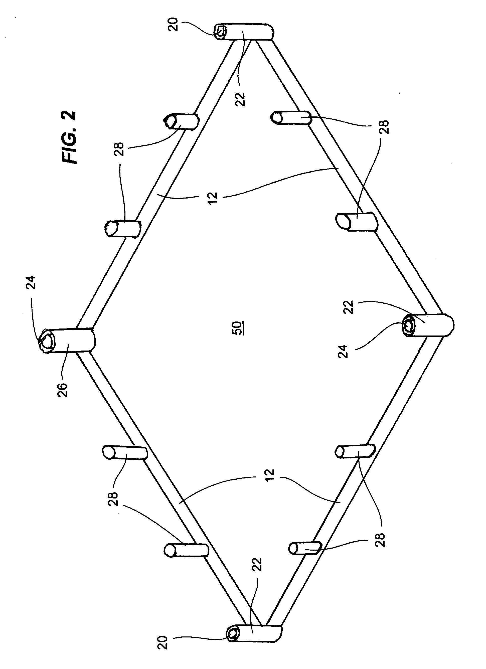
[0014]In view of the foregoing disadvantages inherent in the known devices now present in the prior art, the present invention, which will be described subsequently in greater detail, generally comprises a labyrinth framework made up of tubes interconnected to make a base unit which itself combines with three others by way of a connection hub to make up a master square. Each such master square is then connected to other master squares. Vertical tubes join the lower structure to an upper structure from which is hung a partitioning canvas which traces the path to form the labyrinth. Each tube connects and locks in with the next tube by way of frictional interlock which does not require any tools so that it is easy to set up and knockdown afterward.

Problems solved by technology

The prior art suffers from certain drawbacks such as the fragility of the structure which has weak ground anchoring, “soft” wall which can be lifted as easily as one lifts a curtain or else, over elaborate structure mechanisms which make it hard to assemble or disassemble.

Method used


Image

  • Knockdown labyrinth framework
  • Knockdown labyrinth framework
  • Knockdown labyrinth framework

Examples


Embodiment Construction

[0020]FIG. 1 Orthogonal view of the labyrinth in general.

[0021]FIG. 2 Orthogonal view of the lower section of a base unit.

[0022]FIG. 3 Orthogonal view of the lower section of a master square.

[0023]FIG. 4 Orthogonal exploded view of a connection hub.

[0024]FIG. 5 Orthogonal view of the lower section of four master squares to form a grid.

[0025]FIG. 6 Orthogonal view of the upper section of a base unit.

[0026]FIG. 7 Orthogonal view of the upper section of a master square.

[0027]FIG. 8 Orthogonal view showing how pieces connect between them.

[0028]FIGS. 9a–d Orthogonal view of a series of lower tubes showing some of the combinations of ends they can have.

[0029]FIG. 10abc Orthogonal view of a transverse bar, upper tube, and upper tube.

DETAILED DESCRIPTION OF THE PREFERRED EMBODIMENT

[0030]FIG. 1 A knockdown labyrinth framework (10) has a series of interconnected tubes divided into lower tubes (12), vertical tubes (30), and upper tubes (36). It also has a canvas (14) hanging from an upper stru...


PUM


Abstract

A knockdown labyrinth framework made up of tubes interconnected to make a base unit which itself combines with three others by way of a connection hub to make up a master square. Each such master square is then connected to other master squares. Vertical tubes join the lower structure to an upper structure which has hanging rods from which is hung a partitioning canvas which traces the path to form the labyrinth. Each tube connects and locks in with the next tube by way of frictional interlock which does not require any tools so that it is easy to set up and knockdown afterward.

Description

[0001]This application claims priority based on provisional application 60 / 541,283 filed Feb. 2, 2004BACKGROUND OF THE INVENTION[0002]1. Field of the Invention[0003]The invention relates generally to tubular framework but more particularly to labyrinth or maze made up of interlocking pieces of tubes to create limitless shapes for use in a maze.[0004]2. Background of the Invention[0005]Lifesize mazes have been around for ages and were popular in renaissance Europe as a distraction to royalty. Over the centuries, the concept has evolved and has seen a resurgence in popularity in recent years. Most structures use wire mesh fence as a basic structure and sometimes add an opaque canvas hung on the fence so as to keep the alleys visibly isolated.[0006]The prior art shows various types of structures to make labyrinths easily dismantleable such as for use in county fairs and such where a temporary structure is desired.[0007]For example, U.S. Pat. No. 5,046,720 shows an amusement maze locate...

Claims


Application Information

Patent Timeline
Patent Type & Authority Patents(United States)
IPC IPC(8): A63J11/00
CPCA63J11/00
Inventor SAVAGE, PIERRE
Owner SAVAGE PIERRE
Learn More