Honeycomb structure and process for production thereof

a technology of honeycomb and comb, applied in the field of honeycomb structure, can solve the problems of large thermal stress and crack generation, and achieve the effect of reducing the number of cracks and generating large thermal stress

Inactive Publication Date: 2006-11-21
NGK INSULATORS LTD
View PDF20 Cites 47 Cited by
  • Summary
  • Abstract
  • Description
  • Claims
  • Application Information

AI Technical Summary

Benefits of technology

[0008]In the present invention, at least an inflow port end is preferably sealed to form the flow channel separator. Moreover, for the honeycomb structure of the present invention, a thermal expansion coefficient at 20° C. to 800° C. is preferably 2×10⁻⁶ / ° C. or more. A plurality of honeycomb structural segments are integrated to constitute the honeycomb structure, and the flow channel separator is preferably formed in at least one of the honeycomb structural segments. Furthermore, the honeycomb structure preferably includes a honeycomb structural segment in which a sectional area of the cell in a vertical direction is 900 mm2 to 10000 mm2 Furthermore, a bonding material whose difference from the honeycomb structural segment in the thermal expansion coefficient is 1.5×10⁻⁶ / ° C. or less is used to bond and integrate the honeycomb structural segments. Furthermore, the honeycomb structure of the present invention is preferably formed of one or two or more materials selected from a group consisting of silicon nitride, silicon carbide, a silicon-silicon carbide based composite material, mullite, a silicon carbide-cordierite based composite material, and alumina.

Problems solved by technology

In a honeycomb structure used in such a way, the sharp temperature change of exhaust gas and the local heating of the structure make non-uniform the temperature distribution inside the structure and there have been problems such as crack generation in honeycomb structure and the like.
When the honeycomb structure is used particularly as a DPF, it is necessary to burn the fine carbon particles deposited on the filter to remove the particles and regenerate the filter and, in that case, high temperatures are inevitably generated locally in the filter; as a result, a big thermal stress and cracks have tended to generate.
However, this requires a step of producing many segments and thereafter integrating these segments in order to manufacture one honeycomb structure, and this is not economically favorable especially in a case where the structure needs to be divided into a large number of segments.

Method used


Image

  • Honeycomb structure and process for production thereof
  • Honeycomb structure and process for production thereof
  • Honeycomb structure and process for production thereof

Examples


example 1

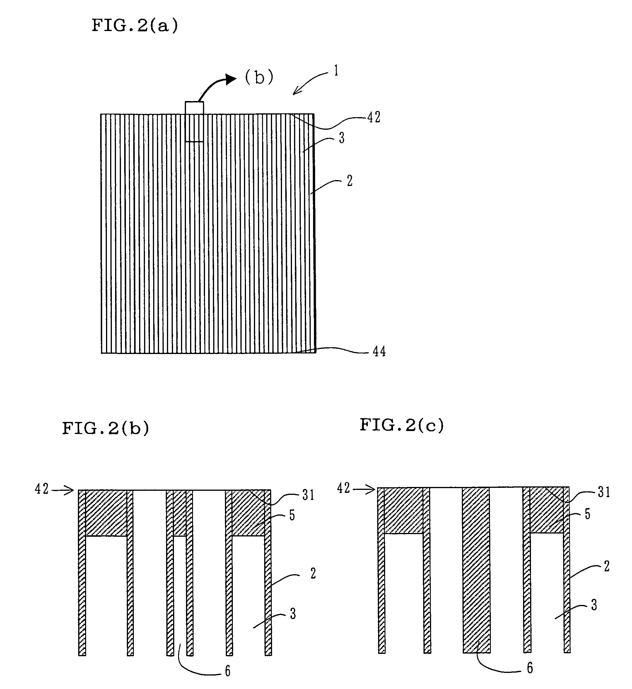
[0052]As a raw material, a mixed powder containing 80% by mass of SiC powder and 20% by mass of metal Si powder was used. To the powder, methyl cellulose, hydroxypropoxyl methyl cellulose, surfactant, and water were added to prepare the puddle having plasticity. This puddle was subjected to extrusion molding, the extrudate was dried using a microwave and hot air to obtain a honeycomb segment having a cell wall thickness of 380 μm, a cell density of 200 cells / in.2 (31.0 cells / cm2), a fun-shaped section which is ¼ of a circle of 144 mm in diameter and a length of 152 mm. In this case, to alternately clog the adjacent cells at the ends on the opposite sides with the material similar to that used in manufacturing the honeycomb structure so that the end surfaces have the checkered patterns, as shown in FIG. 7, the cells continuously arranged in one row are sealed together as shown in FIG. 7, dried, thereafter degreased in an N2 atmosphere at 400° C., and thereafter fired in an Ar inactiv...

example 2

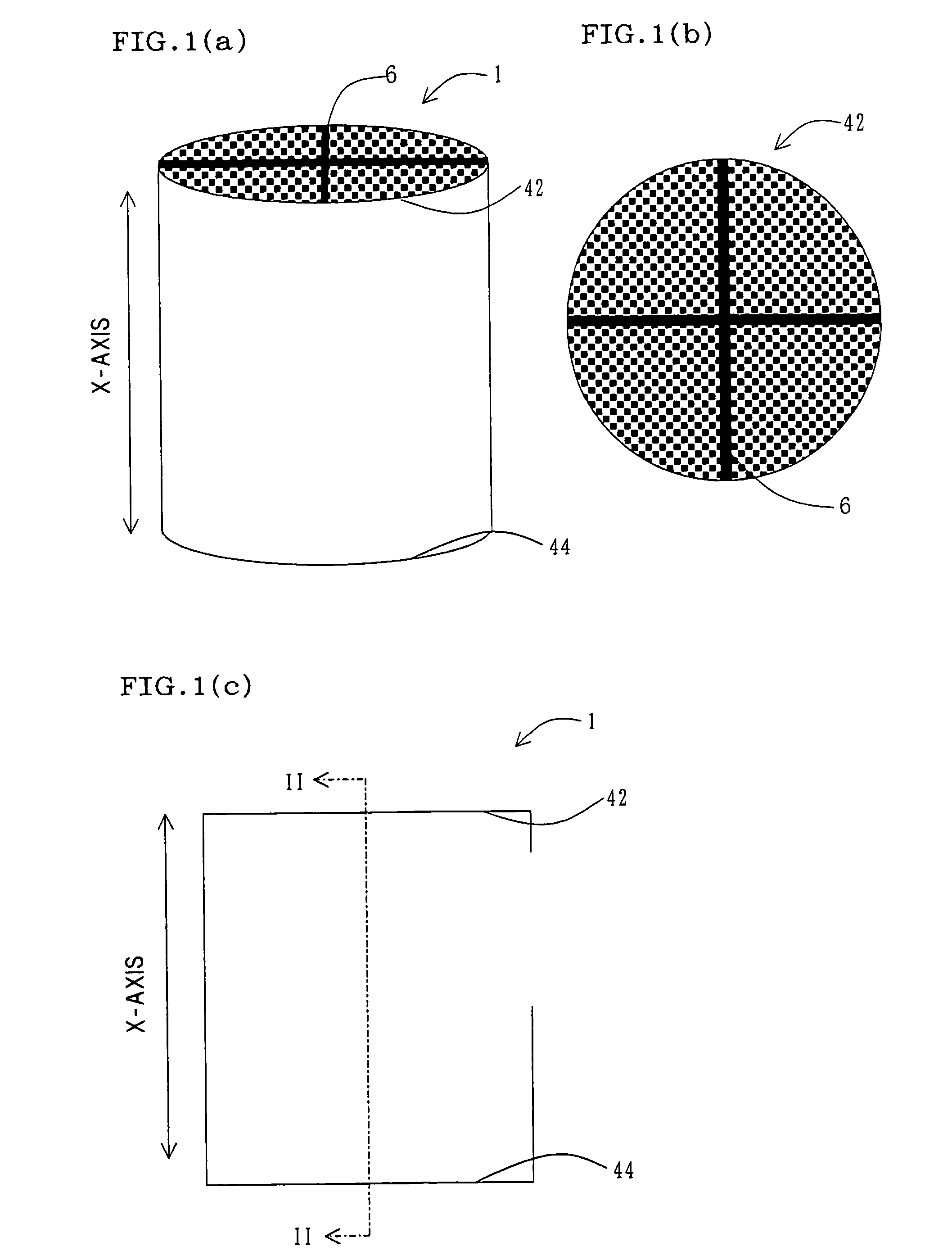
[0054]A columnar honeycomb structure for DPF including the flow channel separator shown in FIG. 8 and having the same size as that of the structure obtained in Example 1 was prepared in the same manner as in Example 1.

example 3

[0055]The puddle was prepared in the same manner as in Example 1, and an integral extruded / molded material (non-segmented molded material) including a cross-shaped 500 μm flow channel separator shown in FIG. 9 was molded (integral forming method). The material was dried, clogged, degreased, and fired in the same manner as in Example 1 except that the sealing method was not used, and the columnar honeycomb structure for DPF having the same size as that of the structure obtained in Example 1 was obtained.


PUM

PropertyMeasurementUnit
areaaaaaaaaaaa
widthaaaaaaaaaa
widthaaaaaaaaaa

Abstract

There is provided a honeycomb structure in which the structure is not segmented, or a smaller number of segments are integrated to suppress a local temperature rise and to reduce breakage by thermal stress at the time of use, and a method of manufacturing the structure. There is disclosed a honeycomb structure 1 comprising: a large number of cells 3 partitioned by cell walls 2 and extending through an axial direction. A flow channel separator 6 is formed in the honeycomb structure 1. There is disclosed a method of manufacturing the honeycomb structure 1 in which the flow channel separator 6 is formed by extrusion. There is disclosed a method of manufacturing the honeycomb structure 1 in which the flow channel separator 6 is formed by clogging.

Description

TECHNICAL FIELD[0001]The present invention relates to a honeycomb structure for use in a filter for capturing particulates in an exhaust gas of an internal combustion engine or a boiler, and a method of manufacturing the structure, particularly to a honeycomb structure which is hardly damaged by a thermal stress at the time of use and which can be manufactured by an economically advantageous process, and the method of manufacturing the structure.BACKGROUND ART[0002]A honeycomb structure has been used in a filter for capturing particulate in exhaust gas of an internal combustion engine or a boiler, particularly used in a filter for capturing diesel particulate (it is hereinafter referred to as DPF) or a substrate for purifying exhaust gas, or the like.[0003]The honeycomb structure for use in this purpose, in general, includes a large number of cells 3 partitioned by cell walls 2 and extending through an X-axis direction as shown in FIGS. 18(a) and 18(b). Furthermore, the structure fo...

Claims


Application Information

Patent Timeline
Patent Type & Authority Patents(United States)
IPC IPC(8): B01D46/00F01N3/02B01D39/20B01D46/24B01D53/86B01J35/04B28B3/26F01N3/022
CPCB01D46/0001B01D46/2448B01D46/2459B01D46/247B01J35/04F01N3/0222B01D46/2429Y10T428/24149B01D46/2444B01D46/2451B01D2046/2492B01D2046/2496F01N2330/30F01N2330/38F01N2450/28Y02T10/20Y10S55/05Y10S264/48Y10S55/30Y10S55/10Y02T10/12B01D46/2498B01D46/2484B01D46/24494B01D46/2478B01D39/20B01D46/00
Inventor HAMANAKA, TOSHIYUKIITO, TADATO
Owner NGK INSULATORS LTD
Why Eureka
Try Eureka