Methods of fabricating polymeric structures incorporating microscale fluidic elements

a technology of micro-fluidic elements and polymeric materials, which is applied in the field of methods of fabricating polymeric structures incorporating micro-fluidic elements, can solve the problems of small reaction time, difficult to accurately manufacture micro-scale structural elements in such polymeric materials, and the amount of reactant transportation and/or mixing is difficul

Inactive Publication Date: 2006-11-21
CAPLIPER LIFE SCI INC
View PDF60 Cites 95 Cited by
  • Summary
  • Abstract
  • Description
  • Claims
  • Application Information

AI Technical Summary

Problems solved by technology

Further, because these devices are of such small scale, the amount of time for reactants to transport and / or mix, is very small.
However, despite these cost advantages, a number of problems exist with respect to the fabrication of microfluidic devices from polymeric materials.
For example, because polymeric materials are generally flexible, a trait that is accentuated under certain fabrication methods, e.g., thermal bonding, solvent bonding and the like, it is difficult to accurately manufacture microscale structural elements in such polymeric materials.

Method used


Image

  • Methods of fabricating polymeric structures incorporating microscale fluidic elements
  • Methods of fabricating polymeric structures incorporating microscale fluidic elements
  • Methods of fabricating polymeric structures incorporating microscale fluidic elements

Examples


example 1

Polymer Selection

[0064]Polymers were selected based upon their clarity, low fluorescence, processability and commercial availability. Several polymer materials were evaluated, as set forth in Table 1, below.

[0065]

TABLE 1PlexiglasMakrolonLexanAcrylite M-30Acrylite L-40VS UVTDP-1-1265OQ1020LProperty(Acrylic)(Acrylic)(Acrylic)(Polycarb.)(Polycarb.)Transmittance9292928990Haze (%)22. . .. . .Melt Flow Rate2428247565(g / 10 min)(all at 230° C.,3.8 kg)Refract. Index1.491.491.491.5821.58Dielectric19.719.7. . .>1614.8–17.6Strength(kV / mm)Vol. Resistivity. . .. . .. . .1.0 × 10161.0 × 1017(Ohm / cm)SupplierCYRO Indust.Cyro Indust.Atohaas,BayerGE PlasticsNorth Am.

Based upon the results shown in Table 1, acrylic polymers, and particularly polymethylmethacrylate were selected as the best polymer substrate, with polycarbonate being the next best selection. Further tests were performed on these polymers and the results are shown in Table 2. Polymer resins were tested using injection molded test plates....

example 2

Thermal Bonding of Polymer Substrates

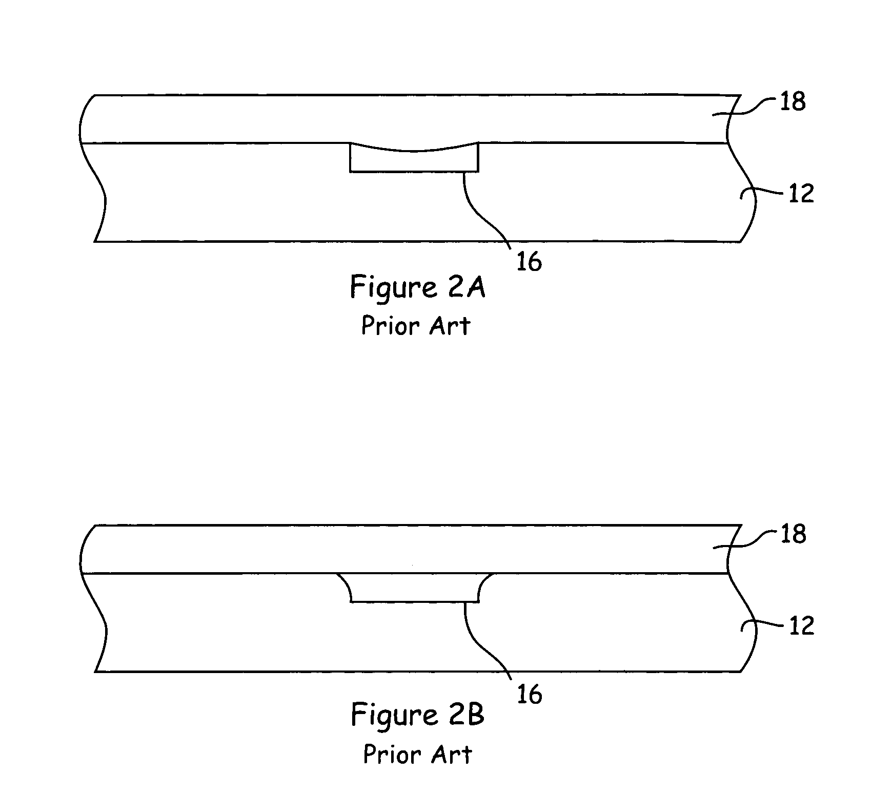
[0068]Initial bonding experiments utilized an embossed channel plate (substrate) fabricated from Plexiglas clear 99530 (described above). The channels had dimensions of 100 μm wide and 32 μm deep. A L-40 PMMA cover plate was thermally bonded to the channel plate at 84° C., the softening point of the L-40 polymer, and with an applied force of approximately 10 kg. Cross-sectional examination of the bonded channel showed that while the embossed channel plate maintained its structure, the cover plate had deformed into the channel, as shown in FIG. 5A. The provided dimensions are approximate. The bonding temperature was then adjusted to 80° C., and the experiment repeated. In this latter experiment, the cross section of the bonded parts showed that the channel had achieved a good seal, the channel was not distorted, nor had the cover plate substantially flowed into the channel as shown in FIG. 5B.


PUM

PropertyMeasurementUnit
heightaaaaaaaaaa
heightaaaaaaaaaa
heightaaaaaaaaaa

Abstract

The present invention generally provides improved methods of fabricating polymeric microfluidic devices that incorporate microscale fluidic structures, whereby the fabrication process does not substantially distort or deform such structures. The methods of the invention generally provide enhanced bonding processes for mating and bonding substrate layers to define the microscale channel networks therebetween.

Description

CROSS-REFERENCE TO RELATED APPLICATION[0001]This application is a division of U.S. patent application Ser. No. 09 / 590,661, filed Jun. 7, 2000, now U.S. Pat. No. 6,555,067 B1, which is a division of U.S. patent application Ser. No. 09 / 073,7 10, filed May 6, 1998, now U.S. Pat. No. 6,123,798.BACKGROUND OF THE INVENTION[0002]As with the electronics and computer industries, trends in chemical and biochemical analysis are moving toward faster, smaller and less expensive systems and methods for performing all types of chemical and biochemical analyses.[0003]The call for smaller systems and faster methods has been answered, in part, through the development of microfluidic technologies, which perform chemical and biochemical analyses and syntheses in extremely small-scale integrated fluid networks. For example, published International Patent Application No. WO 98 / 00231 describes microfluidic devices, systems and methods for performing a large number of screening assays within a single micro...

Claims


Application Information

Patent Timeline
Patent Type & Authority Patents(United States)
IPC IPC(8): B32B37/04B01L3/00B29C65/00B29C65/02B32B38/04B32B38/06G01N27/447
CPCB01L3/502707B07C5/342B29C65/02B29C66/54B29C66/73115B32B37/0023B32B38/06G01N27/44791B29C66/30223Y10T428/2495B29L2031/756B32B2037/0092B32B2310/028B32B2310/0843Y10T428/266Y10T156/10B01L2200/12B29C66/8322B29C65/08B29C66/73365B29C66/73343B29C66/71B29C66/712B29C66/723B29C65/8253B29K2081/06B29K2069/00B29K2067/00B29K2055/02B29K2033/12B29K2027/18B29K2027/14B29K2027/06B29K2023/18B29K2023/12B29K2023/06
Inventor GANDHI, KHUSHROODUBROW, ROBERT S.BOUSSE, LUC J.
Owner CAPLIPER LIFE SCI INC
Why Eureka
Try Eureka