
Method and apparatus for memory redundancy and recovery from uncorrectable errors

a technology of uncorrectable errors and methods, applied in the field of memory redundancy, can solve problems such as multi-bit errors that are typically uncorrectable, single-bit errors that are most often caused, and certain types of single-bit errors that are uncorrectabl

Active Publication Date: 2006-11-21
ORACLE INT CORP
View PDF5 Cites 8 Cited by
  • Summary
  • Abstract
  • Description
  • Claims
  • Application Information

AI Technical Summary

Benefits of technology

This solution enables continuous operation without shutdowns, improves system reliability, and allows for the identification and management of physical errors in memory devices, enabling scheduled replacement rather than immediate shutdown.

Problems solved by technology

Single-bit errors are most often caused by a random transient event.
However, there are certain types of single-bit errors that are uncorrectable.
These uncorrectable single-bit errors are sometimes referred to as “sticky bits.” A “sticky bit” usually is the result of a physical problem in the memory device.
In addition, there are multi-bit errors that are typically uncorrectable.
The multi-bit errors may be the result of a physical problem in the memory device, like a “sticky bit,” or they may be the result of some other random transient event.
Unlike correctable single-bit errors, multi-bit errors and uncorrectable single-bit errors will result in a difference between the data received and the data actually written to the memory device.
For example, in a computer system, receipt and identification of an uncorrectable error will often cause the initiation of a controlled shutdown, including a recordation of the error.
In contrast, operating the system with corrupted data may lead to an uncontrolled shutdown, or “crash.” In any case, uncorrectable errors result in shutdowns that reduce the uptime and availability of the system.

Method used


Image

  • Method and apparatus for memory redundancy and recovery from uncorrectable errors
  • Method and apparatus for memory redundancy and recovery from uncorrectable errors
  • Method and apparatus for memory redundancy and recovery from uncorrectable errors

Examples


Embodiment Construction

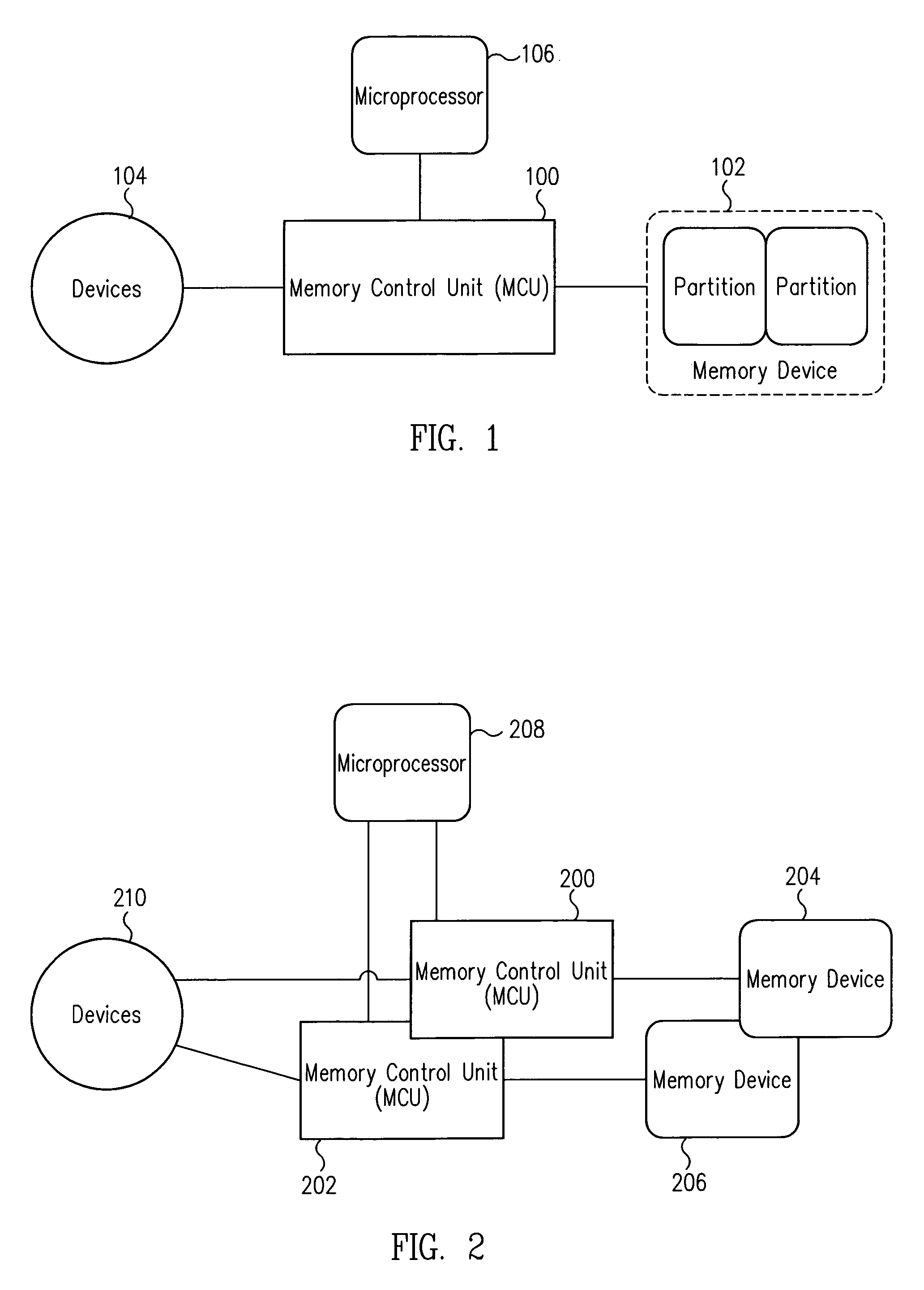
[0014]Embodiments of the present invention are described herein in the context of a computer system with redundant memory units. Those of ordinary skill in the art will realize that the following detailed description of the present invention is illustrative only and is not intended to be in any way limiting. Other embodiments of the present invention will readily suggest themselves to such skilled persons having the benefit of this disclosure. Reference will now be made in detail to implementations of the present invention as illustrated in the accompanying drawings. The reference indicators will be used throughout the drawings and the following detailed description to refer to the same or like parts.

[0015]In the interest of clarity, not all of the routine features of the implementations described herein are shown and described. It will, of course, be appreciated that in the development of any such actual implementation, numerous implementation-specific decisions must be made in ord...


PUM


Abstract

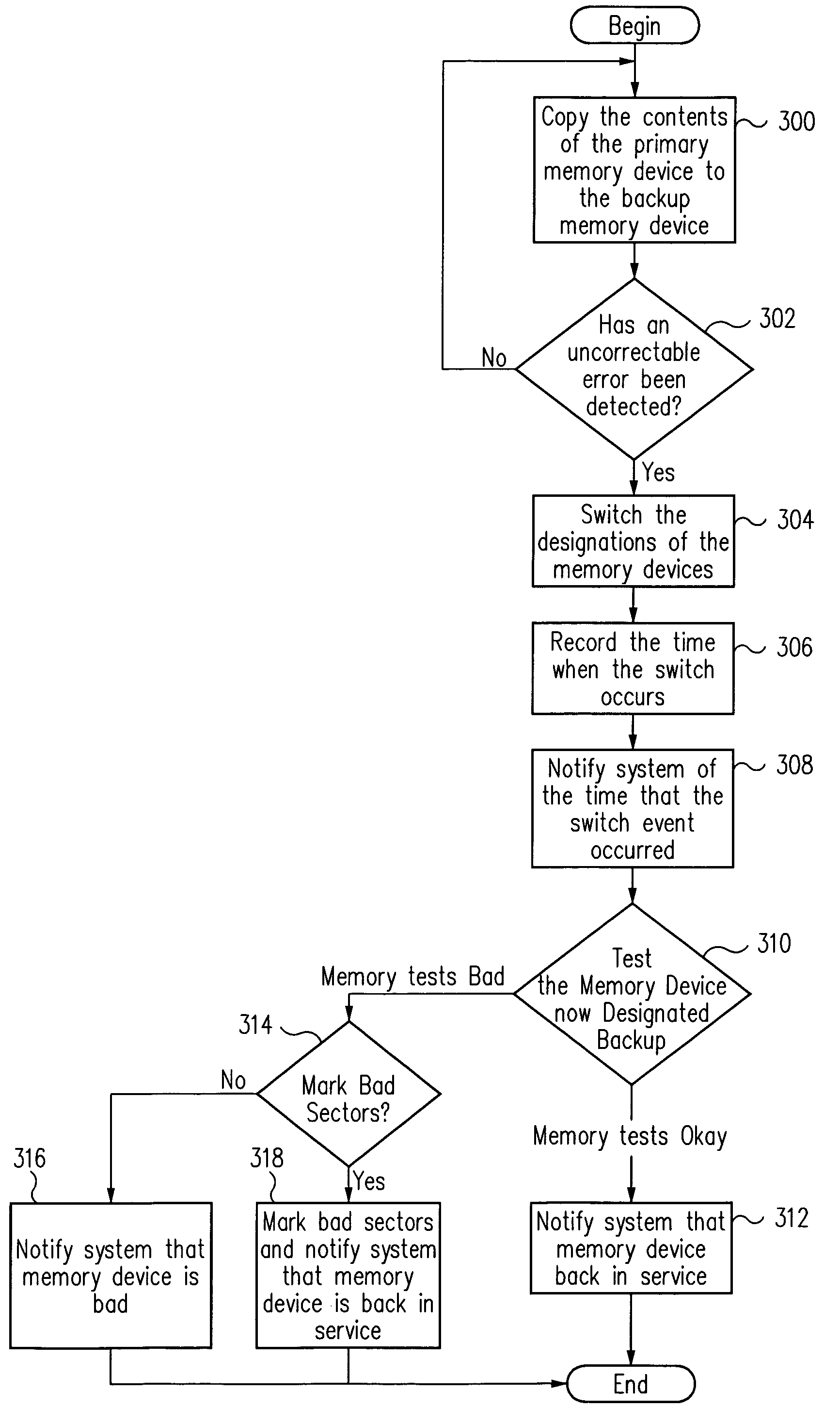
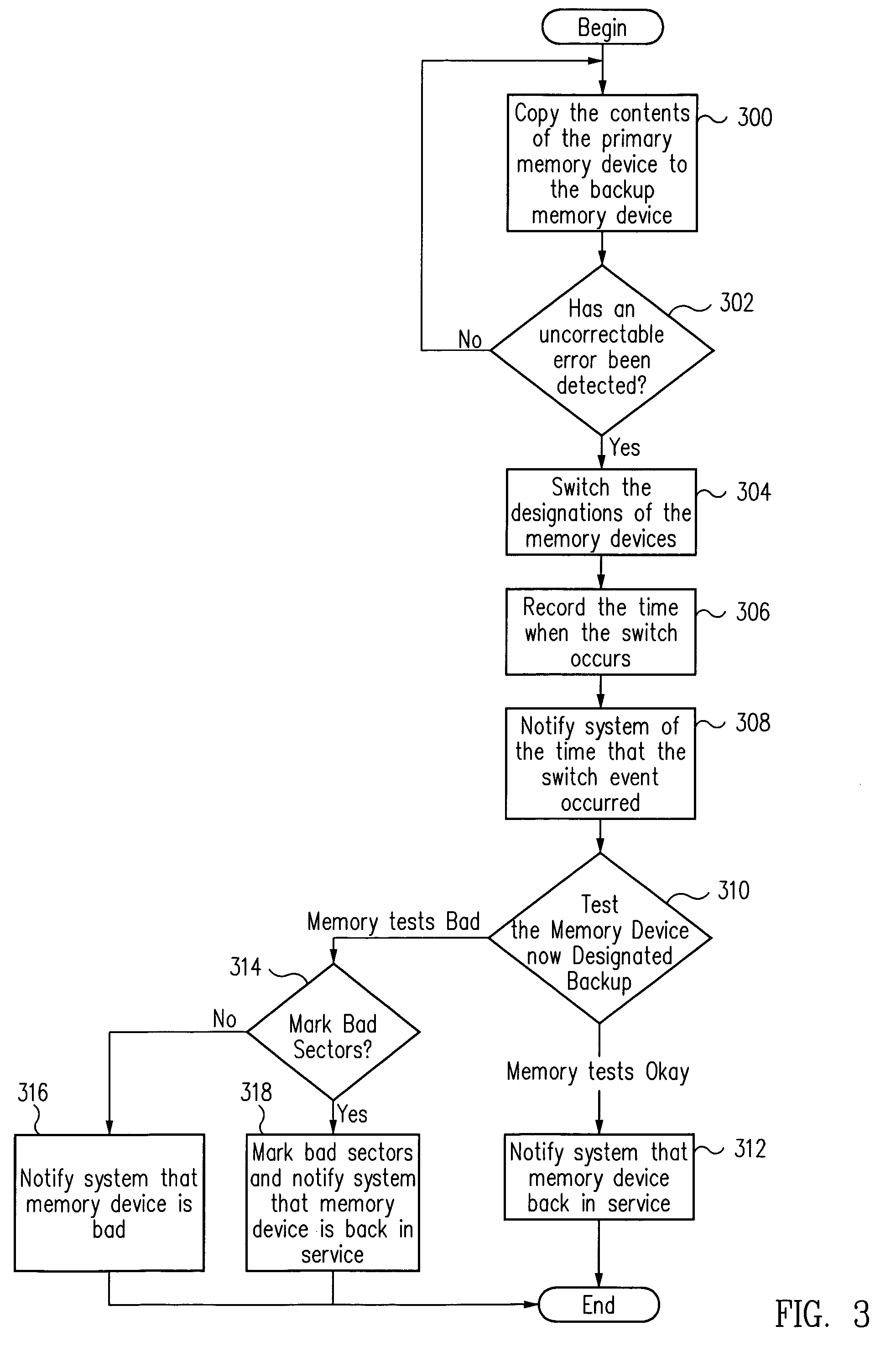
A system maintains a copy of data stored in a first memory device in a redundant distinct second memory device. Upon detecting an uncorrectable error in the first memory device, the system then relies on the copy of the data in the second memory device. The system, once it starts relying on the data in the second memory device, may then test the first memory device to determine if the uncorrectable error was due to a physical problem or a transient event. If the first memory device is then found to be working correctly, it may, in turn, become a redundant memory device for the second memory device.

Description

FIELD OF THE INVENTION[0001]The present invention relates to the field of memory redundancy. More particularly, the present invention relates to maintaining a redundant backup memory system and switching from a primary memory system to the redundant backup memory system upon the occurrence of a fault.BACKGROUND OF THE INVENTION[0002]Typically, systems that make use of electronic data and commands store the data and commands in some sort of memory device. Access to the data stored in the memory device is often controlled by a memory control unit (MCU). In such a system, each individual memory device is assigned to an MCU, and each MCU controls access to its corresponding memory devices. For example, in a computer, when a microprocessor requests data from the computer's Random Access Memory (RAM), the microprocessor sends a request to the MCU corresponding to the RAM, and the MCU fetches the requested data from the RAM and sends it to the microprocessor.[0003]The MCU also controls the...

Claims


Application Information

Patent Timeline
Patent Type & Authority Patents(United States)
IPC IPC(8): G11C29/00G06F11/00G06F11/14G06F11/20
CPCG06F11/1666G06F11/2097G06F11/20
Inventor SUBRAMANIAN, SRINIVASANJOHNSON, JOHN G.ONUFER, GREGORY C.
Owner ORACLE INT CORP
Learn More