Heatshielded article

a technology of heatshields and articles, applied in the direction of lighting and heating apparatus, hot gas positive displacement engine plants, combustion processes, etc., can solve the problems of high cost and complexity of introducing changes, affecting the heatshields of the engine, and not without limitations, so as to improve the heatshields. , the height of the projection can be easily changed, and the heatshields can be easily and inexpensively reoperated. easily and inexpensively

Inactive Publication Date: 2006-11-28
UNITED TECH CORP
View PDF30 Cites 68 Cited by
  • Summary
  • Abstract
  • Description
  • Claims
  • Application Information

AI Technical Summary

Benefits of technology

[0012]One advantage of the invention is that the height of the projection can be easily changed by increasing or decreasing the coating thickness. This allows the manufacturer of the heatshield to easily and inexpensively introduce changes into the manufacturing process for producing new heatshields and to easily and inexpensively reoperate previously manufactured heatshields. A second advantage is that the coating can help mitigate problems related to heat transfer or contact between dissimilar materials at the interface where projections on the heatshield contact the support.

Problems solved by technology

Because of the high temperatures, the liner surfaces that face the hot gases are susceptible to damage.
Despite the advantages of thermally decoupled, impingement film cooled combustors, they are not without certain limitations.
However introducing such changes can be expensive and complicated for the-engine manufacturer.
Additional limitations might affect advanced combustors that use a nickel alloy support shell and a refractory heatshield, especially at the interface where a heatshield boundary wall or other non-penetrating projection contacts the support shell.
This can cause problems such as local oxidation or corrosion of the shell, local excedance of its temperature tolerance or local excedance of its tolerance to temperature gradients.
Other problems related to direct contact include detrimental changes in the morphology or microstructure of the shell, changes that may be exacerbated by elevated temperatures.

Method used


Image

  • Heatshielded article
  • Heatshielded article
  • Heatshielded article

Examples


Embodiment Construction

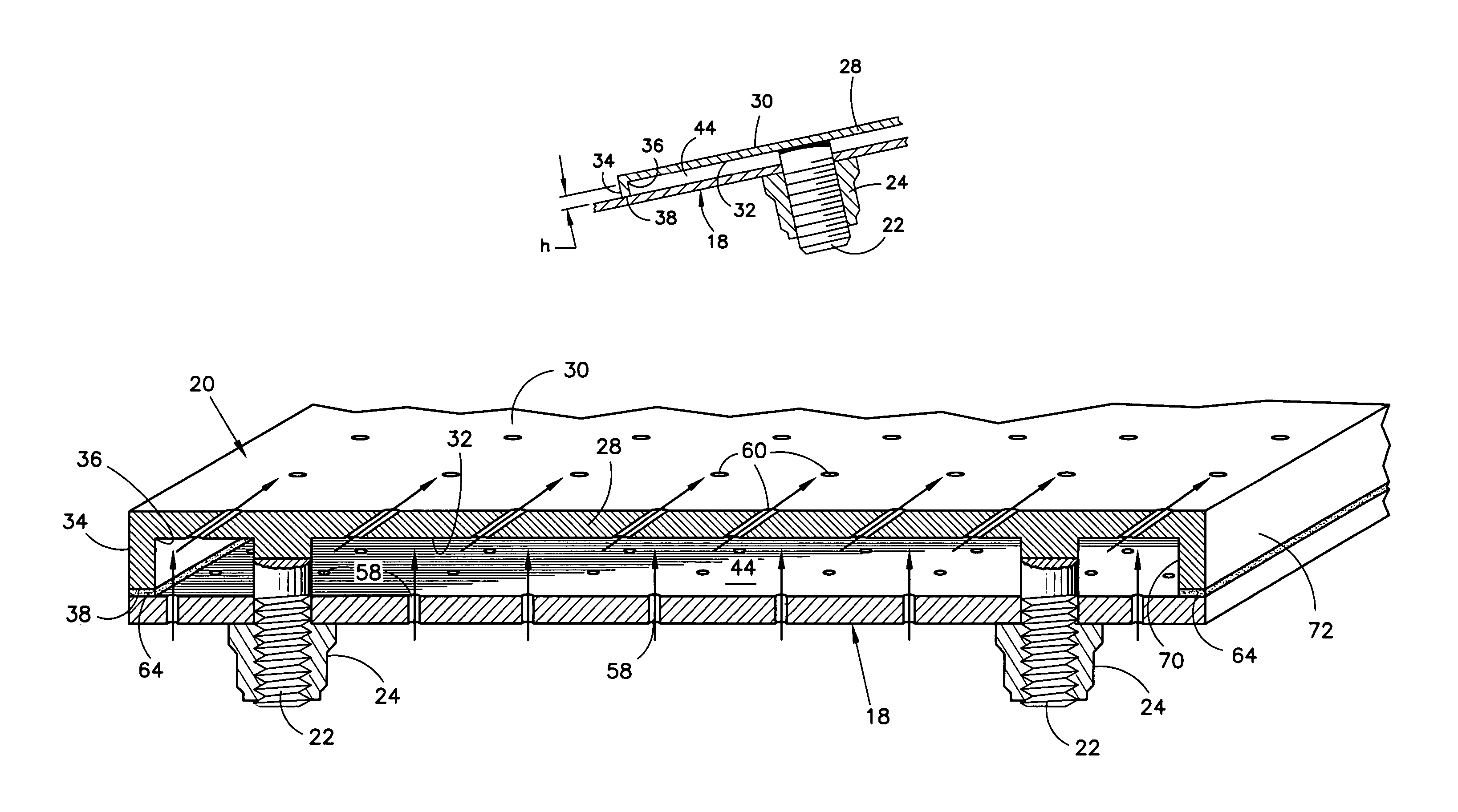
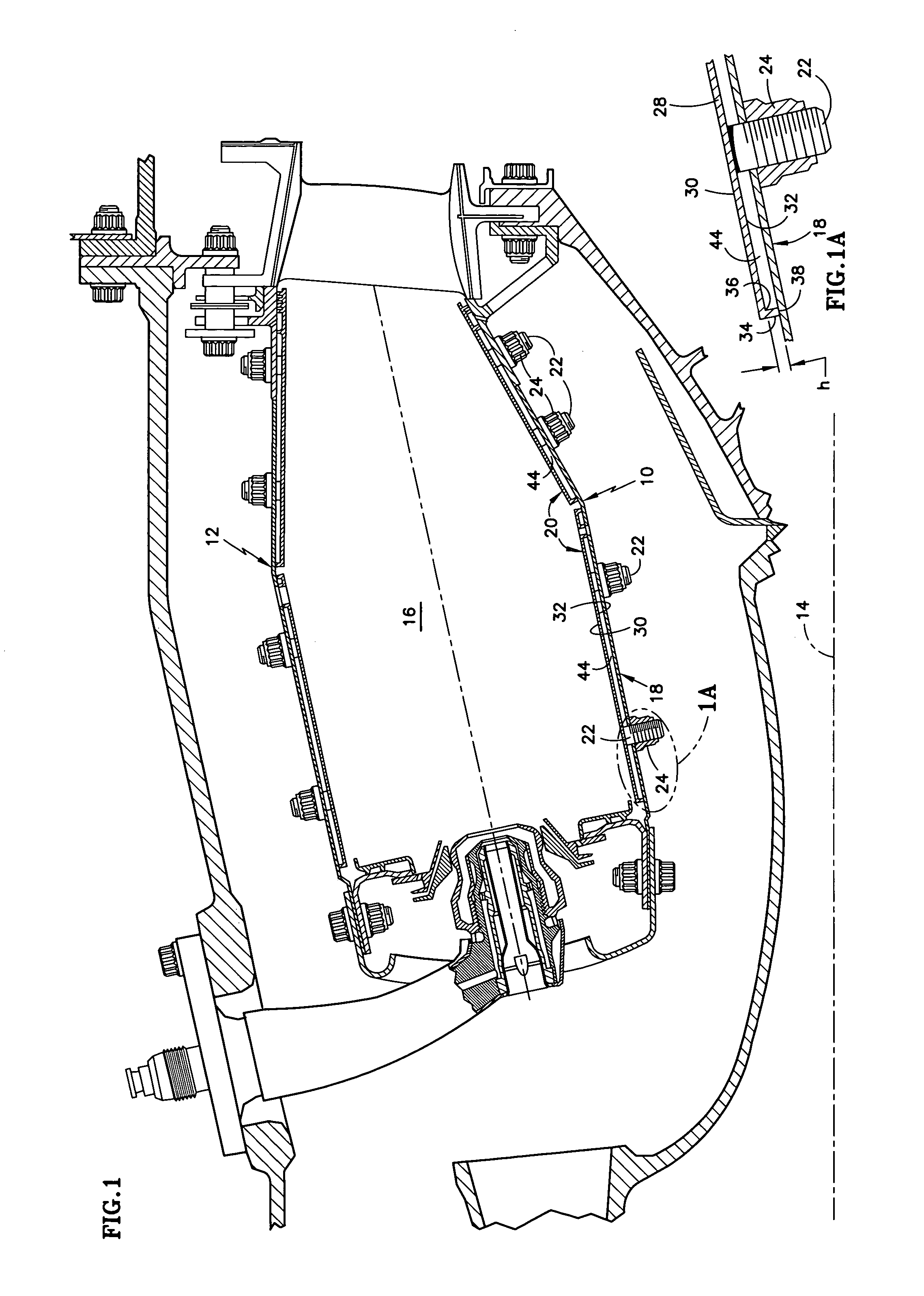
[0019]Referring to FIGS. 1 and 1A, an annular, impingement film cooled combustor for a turbine engine includes radially inner and outer liners 10, 12. Each liner circumscribes an engine axis 14. The liners cooperate with each other to define an annular combustion chamber 16.

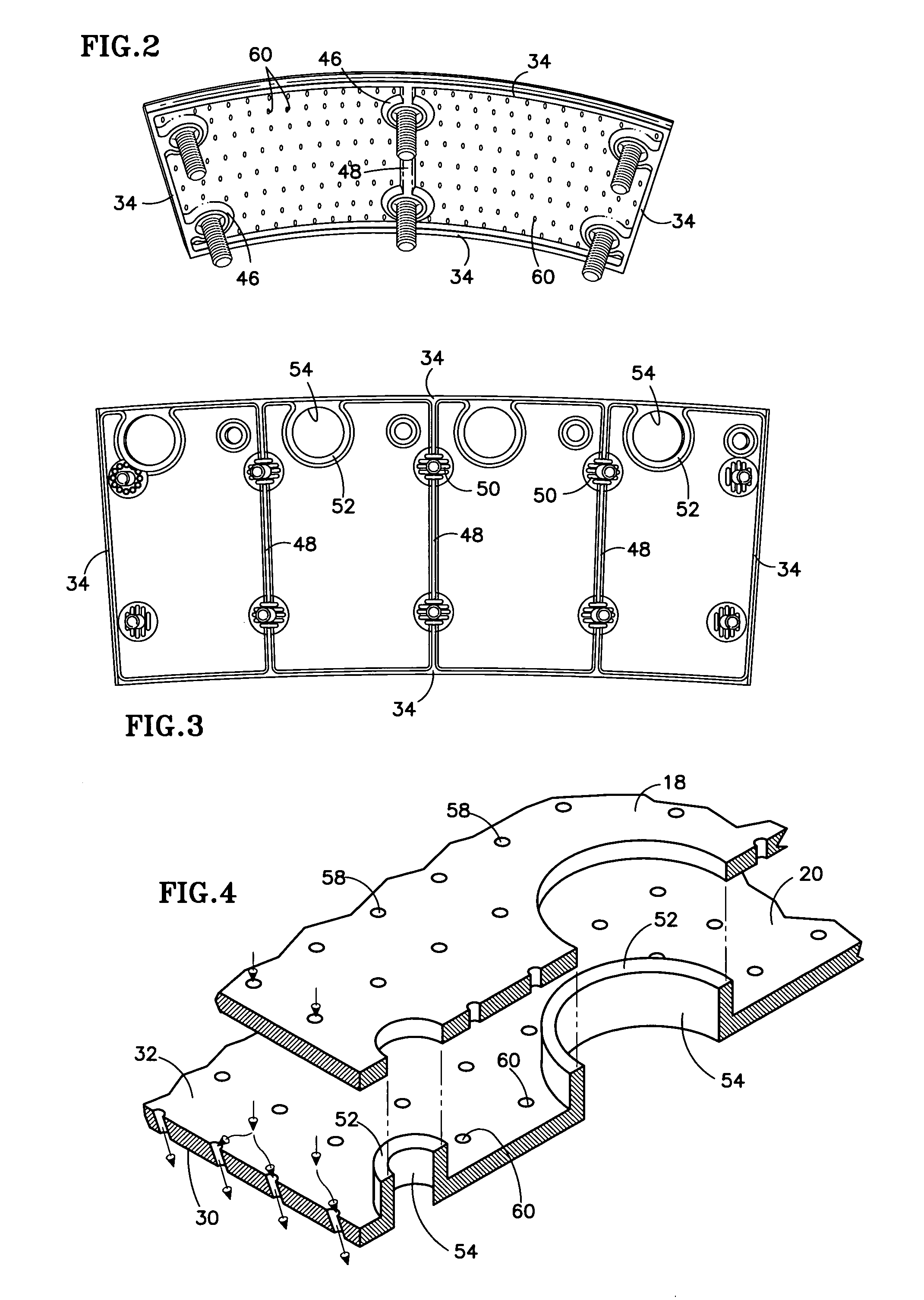
[0020]The inner and outer liners are similar, and it will suffice to describe only the inner liner in greater detail. The inner liner comprises a support shell 18 and a set of axially and circumferentially distributed heatshield panels 20. Threaded studs 22, project from one side of each heatshield and penetrate through openings in the shell. A nut 24 threaded onto each stud secures each heatshield to the shell so that a shield portion 28 of the heatshield is oriented substantially parallel to the shell. When thus assembled, one side of the shield, referred to as the hot side 30, faces the combustion chamber 16. The other side, referred to as the cold side 32, faces the support shell.

[0021]Projections other than ...


PUM


Abstract

A heatshielded article includes a support 18 and at least one heatshield 20 secured adjacent to the support. The heatshield includes a shield portion 28 spaced from the support. The shield portion includes a hot side 30 and an uncoated cold side 32. A projection projects from an origin 36 at the shield portion to a terminus 38 remote from the shield portion. The terminus includes a protective coating 64 along at least a portion of its length.

Description

TECHNICAL FIELD[0001]This invention relates to heatshielded articles, such as a combustion chamber for a gas turbine engine, and to heatshields for such articles.BACKGROUND OF THE INVENTION[0002]A typical gas turbine engine includes one or more compressors, a combustor, and one or more turbines each connected by a shaft to an associated compressor. In most modern engines the combustor is an annular combustor in which a radially inner liner and a radially outer liner cooperate with each other to define an annular combustion chamber. During operation, a high temperature stream of gaseous combustion products flows through the combustion chamber. Because of the high temperatures, the liner surfaces that face the hot gases are susceptible to damage. It is, therefore, customary to protect those surfaces with a film of coolant, a protective coating, a heatshield, or some combination thereof.[0003]One type of combustor is referred to as a thermally decoupled combustor; one type of thermally...

Claims


Application Information

Patent Timeline
Patent Type & Authority Patents(United States)
IPC IPC(8): F02C1/00F02G3/00
CPCF23M5/085F23R3/002F23M2900/05001F23M2900/05004F23R2900/03042F23R2900/03044F23R3/00F23R3/42
Inventor BURD, STEVEN W.
Owner UNITED TECH CORP
Why Eureka
Try Eureka