Gas turbine floating collar

a technology of gas turbines and floating collars, which is applied in the direction of combustion process, jet propulsion plants, lighting and heating apparatus, etc., can solve the problems of high cost of repair and replacement of elaborate parts, and high cost of wear and heat of collars

Active Publication Date: 2006-11-28
PRATT & WHITNEY CANADA CORP
View PDF29 Cites 64 Cited by
  • Summary
  • Abstract
  • Description
  • Claims
  • Application Information

AI Technical Summary

Benefits of technology

[0005]In another aspect, the present invention provides a method of providing a floating collar for a gas turbine engine, the method comprising the steps of providing an annular sheet metal blank; and bending the blank to provide a floating collar having an axial extending annular collar portion, an annular flange portion extending radially from the collar portion and a smooth transition portion between the collar and flange portions.

Problems solved by technology

The collar is subject to wear and heat, and is therefore cast / machined form a heat resistant material.
Such improvement, however, often comes at the expense of economical operation for the operator, as elaborate parts are typically more expensive to repair and replace.

Method used


Image

  • Gas turbine floating collar
  • Gas turbine floating collar
  • Gas turbine floating collar

Examples


Embodiment Construction

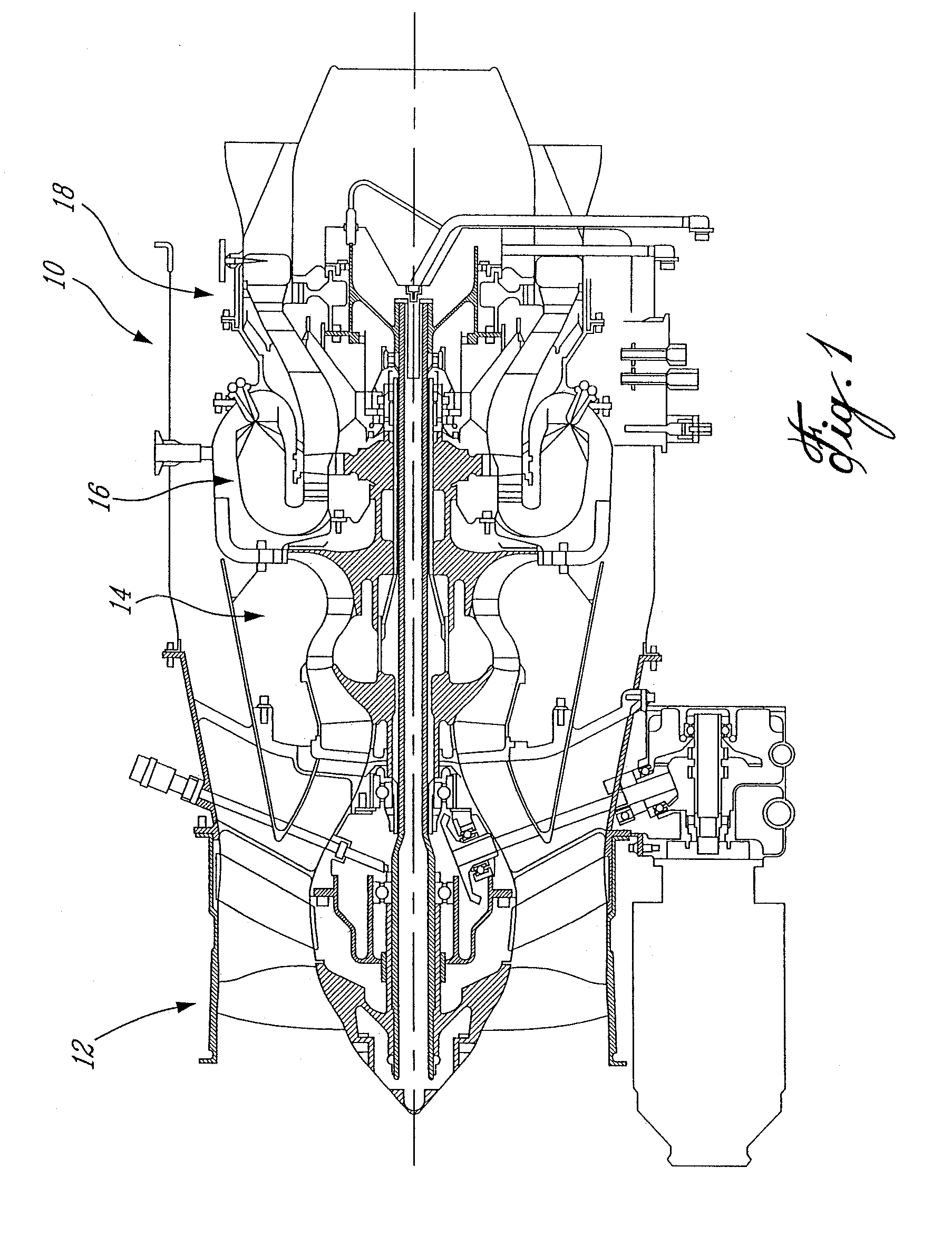
[0012]FIG. 1 illustrates a gas turbine engine 10 of a type preferably provided for use in subsonic flight, generally comprising in serial flow communication a fan 12 through which ambient air is propelled, a multistage compressor 14 for pressurizing the air, a combustor 16 in which the compressed air is mixed with fuel and ignited for generating an annular stream of hot combustion gases, and a turbine section 18 for extracting energy from the combustion gases.

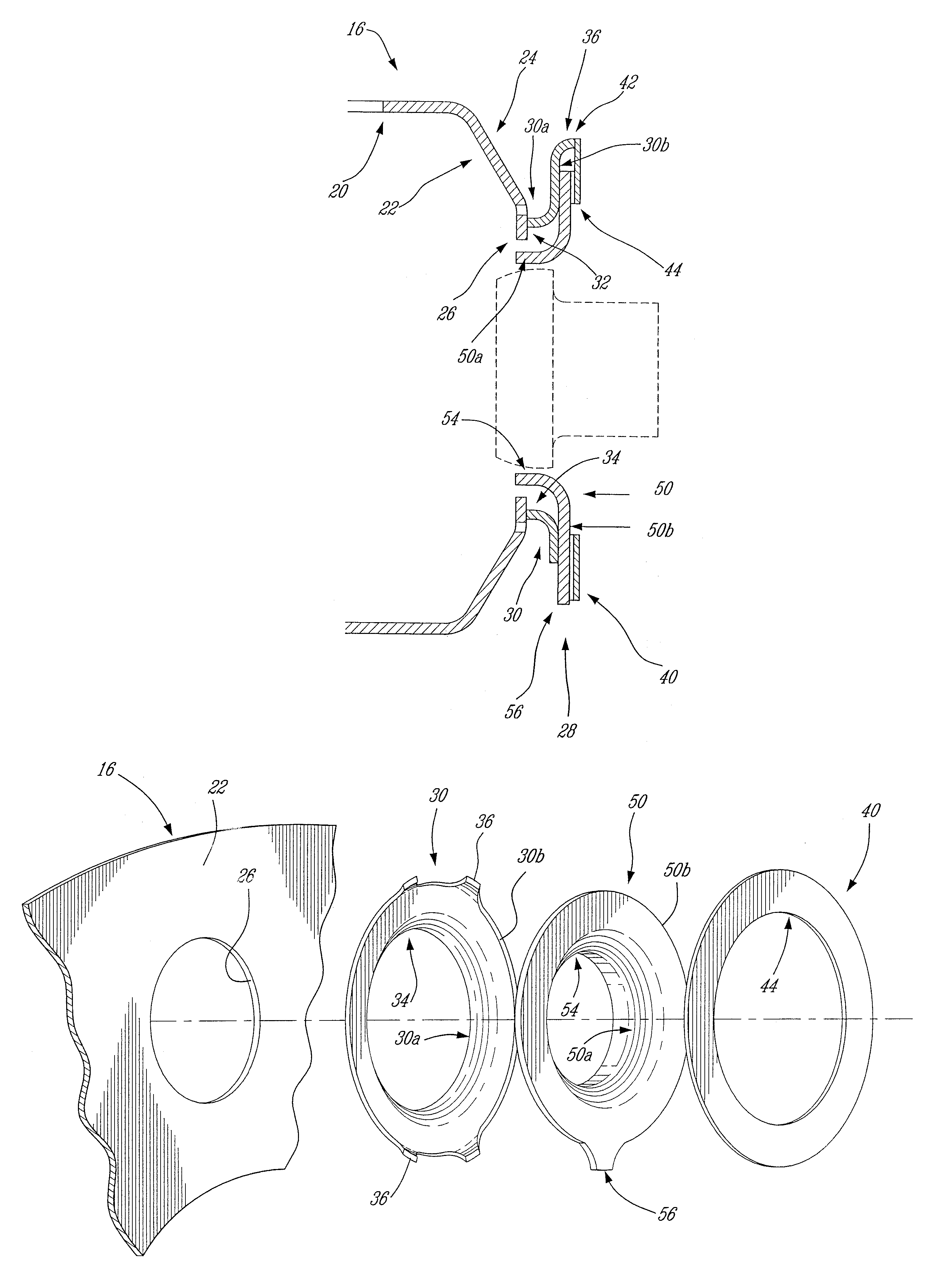
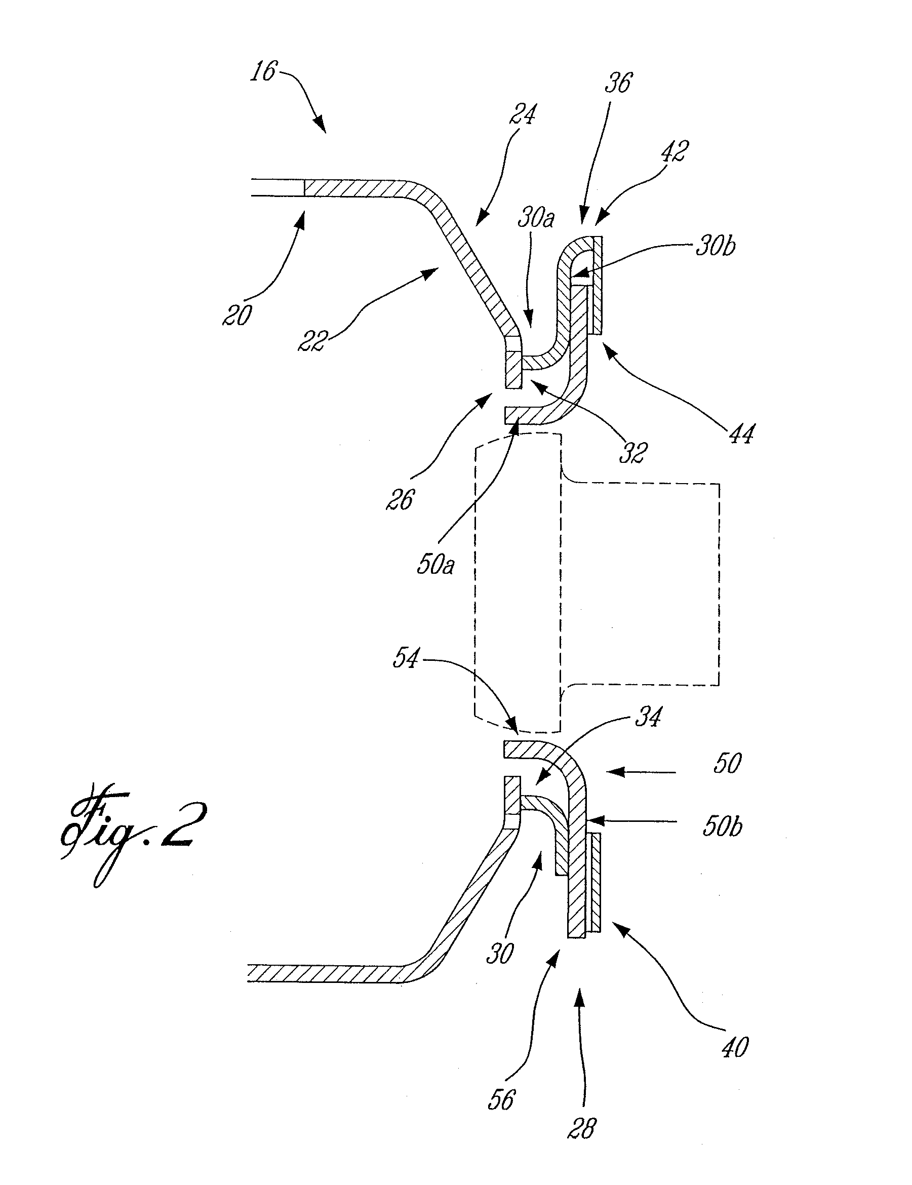
[0013]FIG. 2 shows an enlarged axial sectional view of a combustor 16 having a liner 20 and a dome 22 having an exterior side 24 and a central opening 26 for receiving a air swirler fuel nozzle (depicted in stippled lines in FIG. 2) of the type generally described in U.S. Pat. Nos. 6,289,676 or 6,082,113, for example, and which are incorporated herein by reference. A mounting arrangement 28 is provided as will now be described.

[0014]An annular mounting flange 30 is fixedly bonded, preferably by a weld 32, to the exterior side 2...


PUM

PropertyMeasurementUnit
heat resistantaaaaaaaaaa
energyaaaaaaaaaa
forcesaaaaaaaaaa

Abstract

A simplified floating collar is provided comprising an collar with opposed flanges. The arrangement offers reduced cost, and simplicity, and therefore facilitates manufacturing.

Description

CROSS-REFERENCE TO RELATED APPLICATIONS[0001]This application relates to U.S. patent application entitled GAS TURBINE FLOATING COLLAR ARRANGEMENT and having Ser. No. 10 / 924,208 , filed simultaneously herewith, the specification of which is incorporated herein by reference.TECHNICAL FIELD[0002]The invention relates generally to gas turbine engine combustors and, more particularly, to a floating collar therefor.BACKGROUND OF THE ART[0003]Gas turbine combustors are typically provided with floating collars or seals to permit relative radial or lateral motion between the combustor and the fuel nozzle while minimizing leakage therebetween. The collar is subject to wear and heat, and is therefore cast / machined form a heat resistant material. As fuel nozzles, combustors and related components must be periodically removed for cleaning, inspection, repair and, occasionally replacement, the floating collar arrangement is provided in a manner which facilitates such removal, to thereby facilitat...

Claims


Application Information

Patent Timeline
Patent Type & Authority Patents(United States)
IPC IPC(8): F02C7/20
CPCF23R3/10F23R3/60Y10T29/49346F23R2900/00012
Inventor MARKARIAN, LORINPATEL, BHAWAN BHAL
Owner PRATT & WHITNEY CANADA CORP
Why Eureka
Try Eureka