The knife plates of the brace-side member are secured in place relative to a load-bearing member, or “core,” of a seismic brace. For example, the knife plates may be welded directly to the core or to an intermediate member which is, in turn, welded to the core. These arrangements facilitate the positioning of an end of a yielding core closer to the structural
steel frame than do conventional, rigid connections, which typically consume a significant portion of the fixed distance between brace connection locations. Thus, nonrigid connection apparatus according to the present invention may facilitate the use of seismic braces which include yielding cores that are longer than the yielding cores of conventional seismic braces that may be used at the same location of a structural
steel frame. As is well known in the art, an increase in the length of a yielding core means that the
strain rate on the yielding core will be less, resulting in a fatigue life which is longer than the fatigue life of a similar brace secured at a similar location using conventional, rigid connection apparatus.
Of course, other arrangements and configurations of apparatus for nonrigidly connecting seismic braces to steel structural frames are also within the scope of the present invention. For example, another embodiment of nonrigid connection apparatus that incorporates teachings of the present invention may comprise a ball-and-socket type connection apparatus. The first member, or frame-side member, of such a connection apparatus, which is securable to a steel structural frame, may comprise a socket. The socket may, for example, be in the form of an aperture with a concave edge. The
coupling member of such a connection apparatus may comprise a ball, which may be spherical in shape, an oblong
spheroid, disc-shaped, or otherwise configured to fit within the socket of the frame-side member and rotate somewhat relative to the frame-side member. The
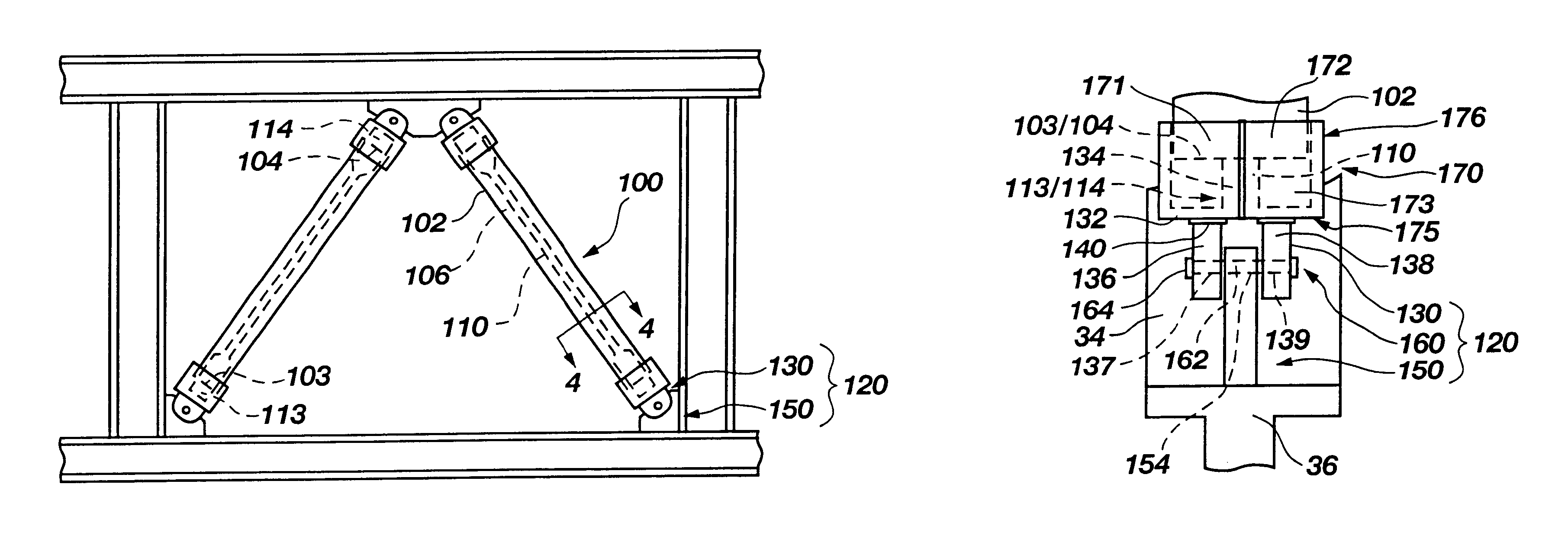
coupling member may also include one or more pins protruding from opposite sides thereof. The second member, or brace-side member, of a ball-and-socket type connection apparatus includes a pair of substantially planar members which are spaced apart a sufficient distance that the ball of the coupling member may be positioned therebetween. An aperture formed through each substantially planar member is configured to receive a portion of a pin protruding from the ball and, thus, facilitates hinged movement of the brace-side member and of a seismic brace to which the brace-side member is secured relative to one or both of the ball and the frame-side member of the connection apparatus.
In use, the frame-side member of a nonrigid connection apparatus of the present invention is secured to a steel structural frame, such as in a corner formed between conjoined horizontal beams and vertical
steel columns. Continuing with the above examples, this may be effected by
welding or otherwise securing one or more gusset plates into such a corner. The brace-side member of the nonrigid connection apparatus, which, preferably, has already been secured to or formed at the end of a core of a seismic brace, is then positioned appropriately relative to the frame-side member, such that apertures of the frame-side and brace-side members are substantially mutually aligned. A coupling member is then introduced into the aligned apertures so as to be positioned within each of the substantially aligned apertures of the frame-side and brace-side members. The coupling member is then secured in this position to prevent inadvertent removal thereof from the apertures. The opposite end of the seismic brace may then be similarly secured to another (higher or lower) horizontally extending steel beam. Alternatively, another type of connection, including a rigid, conventional connection, may be used to secure the other end of the seismic brace to the other horizontally extending beam. As a single pin is secured in position rather than several bolts, as required by conventional, rigid connection apparatus, erection of a seismic brace that includes a nonrigid connection apparatus according to the present invention is simpler and faster than erection with conventional, rigid connection apparatus.
When a building that includes a frame with one or more seismic braces connected thereto by way of a nonrigid connection apparatus of the present invention is subjected to a load, such as that generated by shock
waves (e.g., seismic shock
waves, high winds, etc.), the nonrigid connection apparatus and the adjacent end of the seismic brace are substantially isolated from external moments that result from movement of the seismic brace out of the plane of the bay of a steel structural frame in which the seismic brace is located. The collar resists in-plane and out-of-plane moments on the exposed portions of the core of the seismic brace, as well as of the remainder of the nonrigid connection apparatus, thereby permitting only substantially axial loads to be applied to the core, providing support to the core and the remainder of the nonrigid connection apparatus, and preventing weak axis buckling of the core. In addition, the nonrigid connection apparatus reduces the moments and shears that result from the application of gravity and earthquake loads to a steel structural frame by providing a larger
moment of inertia at the ends of the core of a seismic brace. As a result, the nonrigid connection element substantially limits the forces that are applied to the seismic brace to those which may be properly absorbed thereby.
As a further result of providing a nonrigid connection, the likelihood of a nonrigid connection apparatus according to the present invention being damaged when subjected to gravity and earthquake loads is much lower than the likelihood of a conventional rigid connection being damaged. Thus, following failure due to absorption of excessive earthquake loads, a seismic brace which is at least partially secured to a steel structural frame by way of one or more of the inventive nonrigid connection apparatus may still have some load-bearing capabilities and, thus, provide some structural support to a steel structural frame, whereas seismic braces that are secured in place by weakened conventional rigid connections would be less likely to provide such support.

