
Pinion and rack drilling rig derrick structure and installation method thereof

A technology of rack and pinion and derrick, which is applied in the direction of drilling equipment, earthwork drilling and support devices, etc., which can solve the problems of unbalanced force of rack and pinion, affecting the drilling force of the drilling rig, and affecting the drilling efficiency, so as to ensure the stability , Reduce weight, improve stability and structural strength

Pending Publication Date: 2019-02-22
中石化四机石油机械有限公司 +1
View PDF1 Cites 1 Cited by
  • Summary
  • Abstract
  • Description
  • Claims
  • Application Information

AI Technical Summary

Problems solved by technology

The above-mentioned installation method will cause unbalanced force during the meshing process of the rack and pinion, which is prone to jamming problems, and affects the drilling force of the drilling rig, thereby affecting the drilling efficiency

Method used


Image

  • Pinion and rack drilling rig derrick structure and installation method thereof
  • Pinion and rack drilling rig derrick structure and installation method thereof
  • Pinion and rack drilling rig derrick structure and installation method thereof

Examples


Embodiment 1

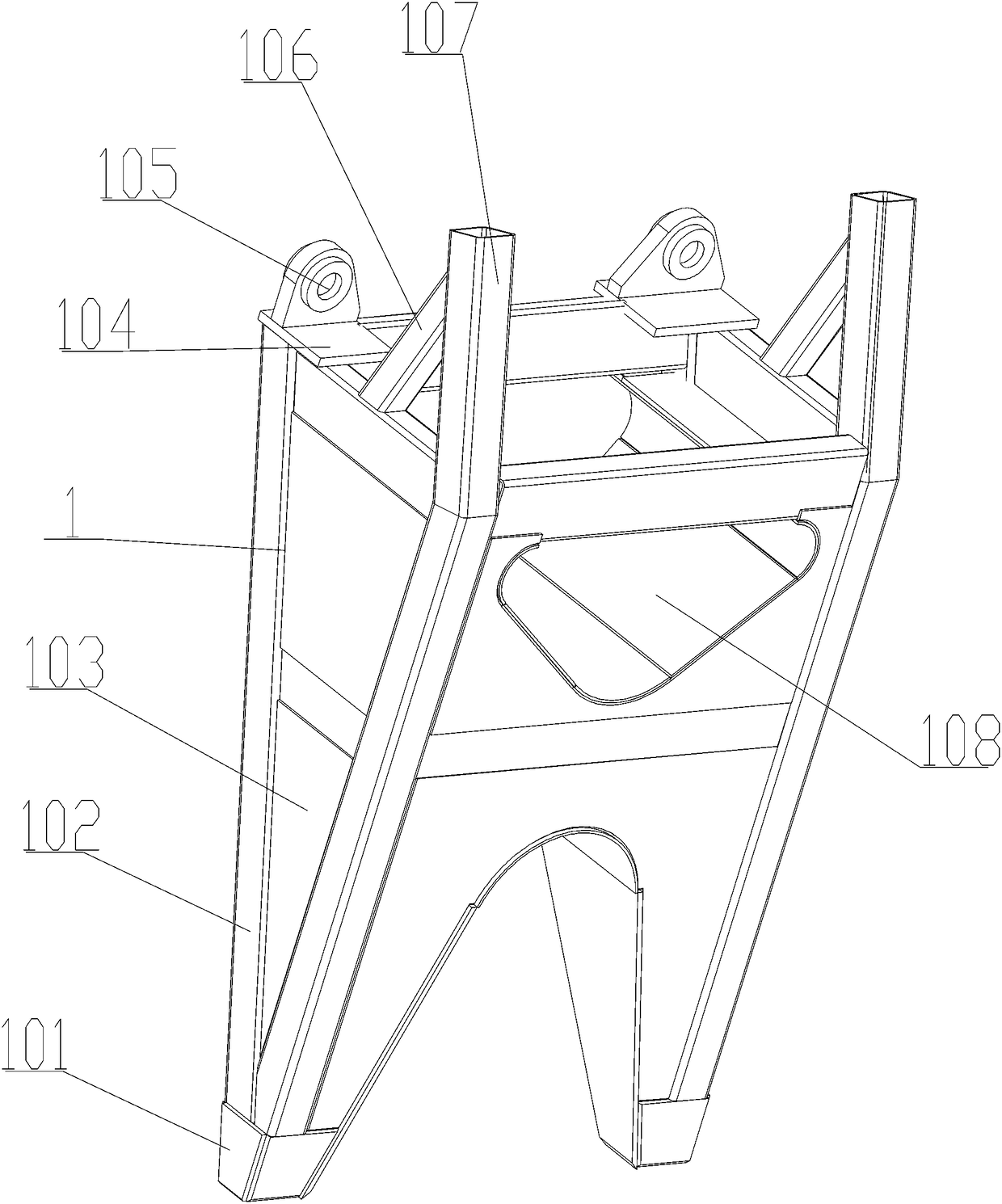
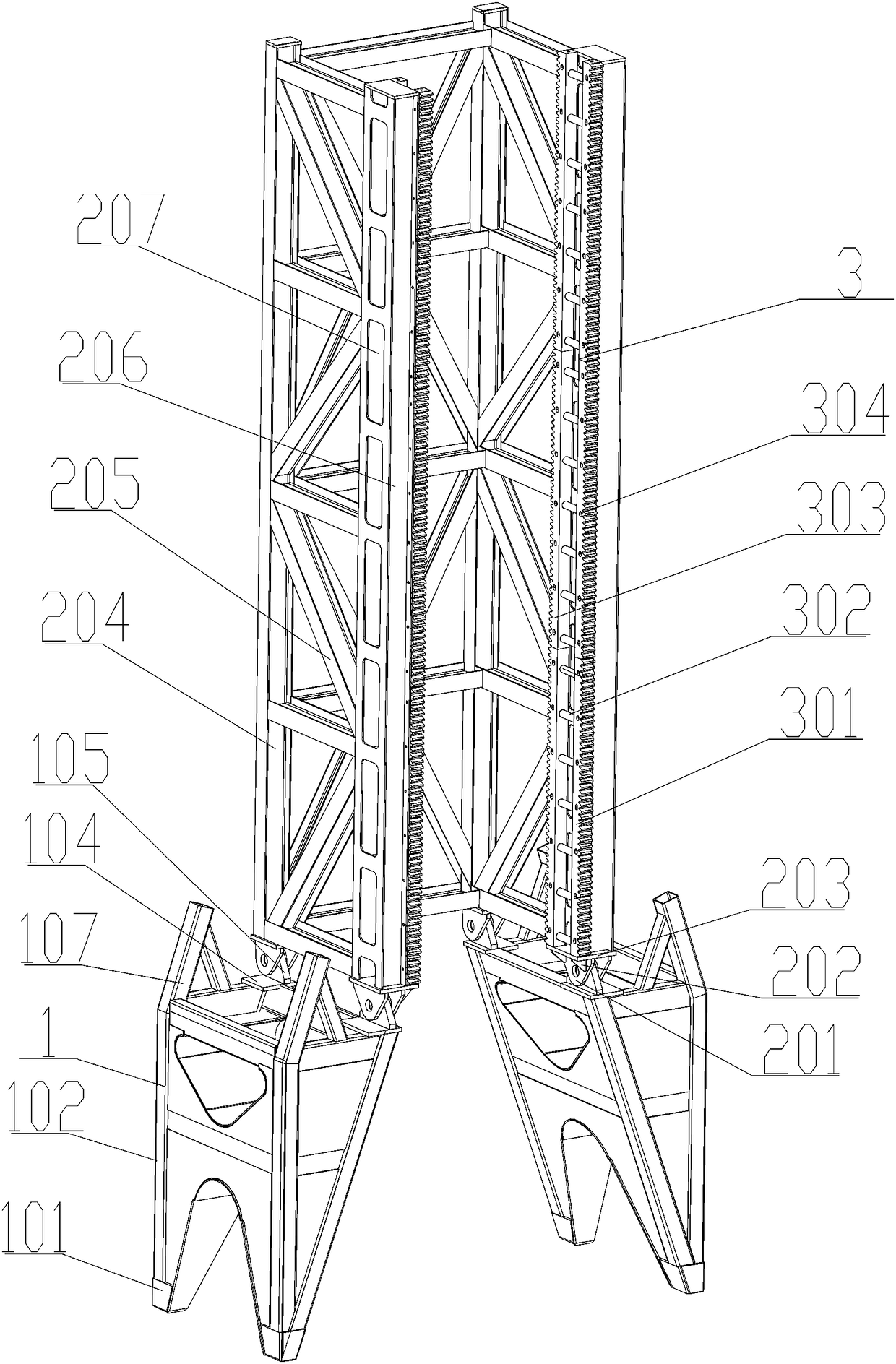
[0035] see Figure 1-5 , a rack and pinion drilling rig derrick structure, which includes a bottom support frame 1 connected to the foundation support at the bottom of the vertical shaft, the bottom support frame 1 is symmetrically arranged, and a bottom section derrick 2 is installed on the top of the two bottom support frames 1. The top of the bottom section derrick 2 is supported by a multi-section intermediate section derrick 5, and the top section derrick 7 is fixedly installed on the top of the top middle section derrick 5; the bottom section rack assembly is fixedly installed on the inner wall of the bottom section derrick 2 3. The middle section rack assembly 4 is fixedly installed on the inner wall of the middle section mast 5 , and the top section rack assembly 6 is fixedly installed on the inner wall of the top section mast 7 . The derrick structure with the above structure can be used for the support and installation of the rack and pinion drilling rig, and the rac...

Embodiment 2

[0042] The installation method of any one of the rack and pinion drilling rig derrick structure, it comprises the following steps:

[0043] Step1: Fix the two symmetrically arranged bottom support frames 1 to the installation foundation at the bottom of the well;

[0044] Step2: Fix the bottom section derrick 2 on the top of the bottom support frame 1;

[0045] Step3: According to the depth of the well, select an appropriate number of middle section derricks 5, and install them on the top of the bottom section derrick 2;

[0046] Step4: Fix the top section derrick 7 on the top of the middle section derrick 5;

[0047] Step5: Fix the bottom section rack assembly 3 , the middle section rack assembly 4 and the top section rack assembly 6 on the inner side walls of the corresponding bottom section derrick 2 , middle section derrick 5 and top section derrick 7 .


PUM


Abstract

The invention discloses a pinion and rack drilling rig derrick structure and an installation method thereof. A bottom section derrick is installed at the tops of two bottom support frames, the top ofthe bottom section derrick is provided with a plurality of sections of middle section derricks in a supported mode, and the top of the topmost middle section derrick is fixedly provided with a top section derrick; and the inner wall of the bottom section derrick is fixedly provided with a bottom section rack assembly, the inner wall of each middle section derrick is fixedly provided with a middlesection rack assembly, and the inner wall of the top section derrick is fixedly provided with a top section rack assembly. The derrick structure adopting the stricture can be used for supporting and installing of a pinion and rack drilling rig, the rack assemblies are symmetrically installed inside the derricks, the rack assemblies adopt symmetrical structures, thus it is ensured that a drilling rig trolley can be engaged with the rack assemblies for transmission, and then stability of transmission of the drilling rig trolley is ensured, so that generated unbalanced force of the drilling rig trolley in the climbing process is effectively prevented.

Description

technical field [0001] The invention relates to a rack and pinion drilling rig derrick structure and an installation method, belonging to the field of drilling rig frame devices. Background technique [0002] The rack on the derrick of the existing rack and pinion drilling rig is installed on the inner wall of the derrick. For example, CN 103397849 A discloses a rack and pinion derrick for inclined straight wells. The rack of this derrick structure is fixed and installed on the side wall. . The above-mentioned installation method will cause an unbalanced force during the meshing process of the rack and pinion, which is prone to jamming, and affects the drilling force of the drilling rig, thereby affecting the drilling efficiency. Contents of the invention [0003] The main purpose of the present invention is to provide a rack and pinion drilling rig derrick structure and its installation method. The racks of the rack and pinion drilling rig derrick structure adopt a symme...

Claims


Application Information

Patent Timeline
IPC IPC(8): E21B15/00
CPCE21B15/00
Inventor 金宗祥陈新龙彭太锋徐军李建平熊先杰朱颢李光金
Owner 中石化四机石油机械有限公司
Learn More