Optical apparatus and method for comprehensive eye diagnosis

a comprehensive eye diagnosis and optical equipment technology, applied in the field of optical inspection instruments, can solve the problems of not being able to integrate visual field tests and oct together, unable to follow the progression of diseases, and the oct imaging method has certain technical difficulties in accurately measuring the rnfl

a comprehensive eye diagnosis and optical equipment technology, applied in the field of optical inspection instruments, can solve the problems of not being able to integrate visual field tests and oct together, unable to follow the progression of diseases, and the oct imaging method has certain technical difficulties in accurately measuring the rnfl

US7140730B2Active Publication Date: 2006-11-28OPTOVUE

Image

  • Optical apparatus and method for comprehensive eye diagnosis
  • Optical apparatus and method for comprehensive eye diagnosis
  • Optical apparatus and method for comprehensive eye diagnosis

Examples


Embodiment Construction

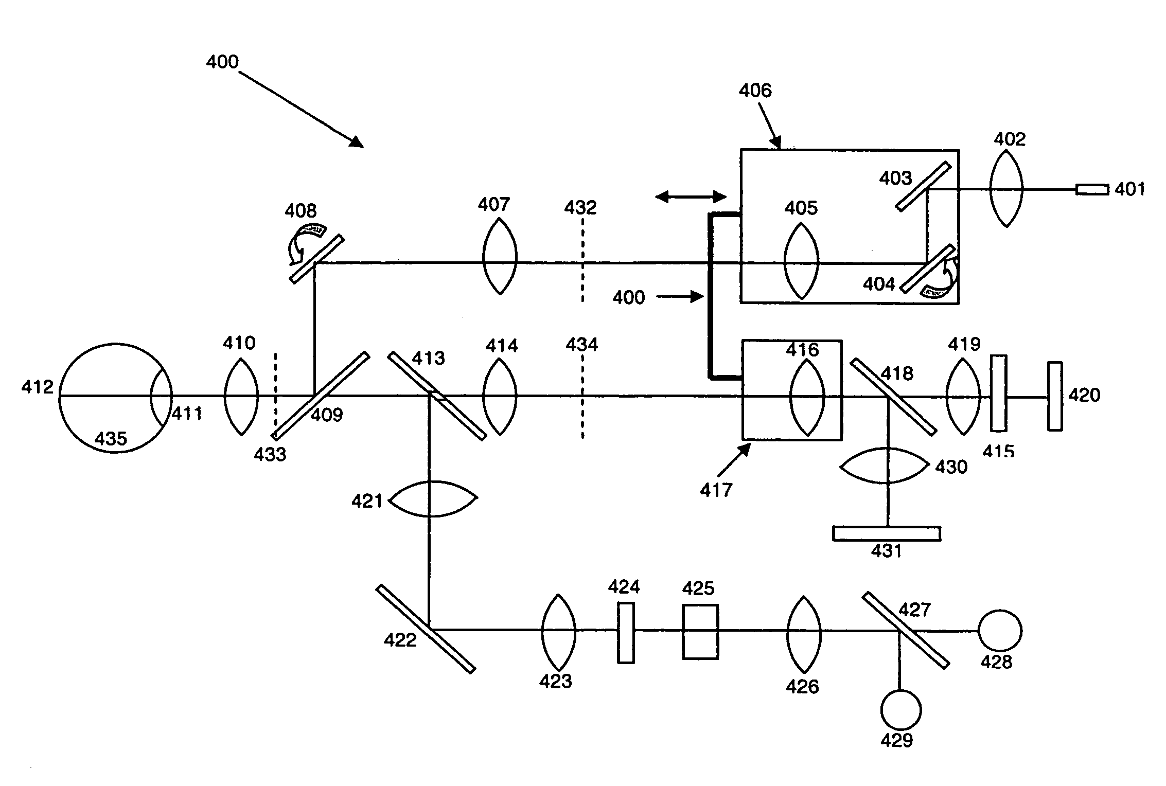
[0022]In accordance with the current invention, an optical apparatus for diagnosis of eye diseases is presented. Some embodiments of optical scanner according to the present invention can be used for non-invasive retinal scanning, retinal imaging with an optical imaging system, and human visual field testing with an optical illumination system. Some embodiments of the current invention are further related to the method for a comprehensive eye exam related to eye diseases such as, for example, glaucoma.

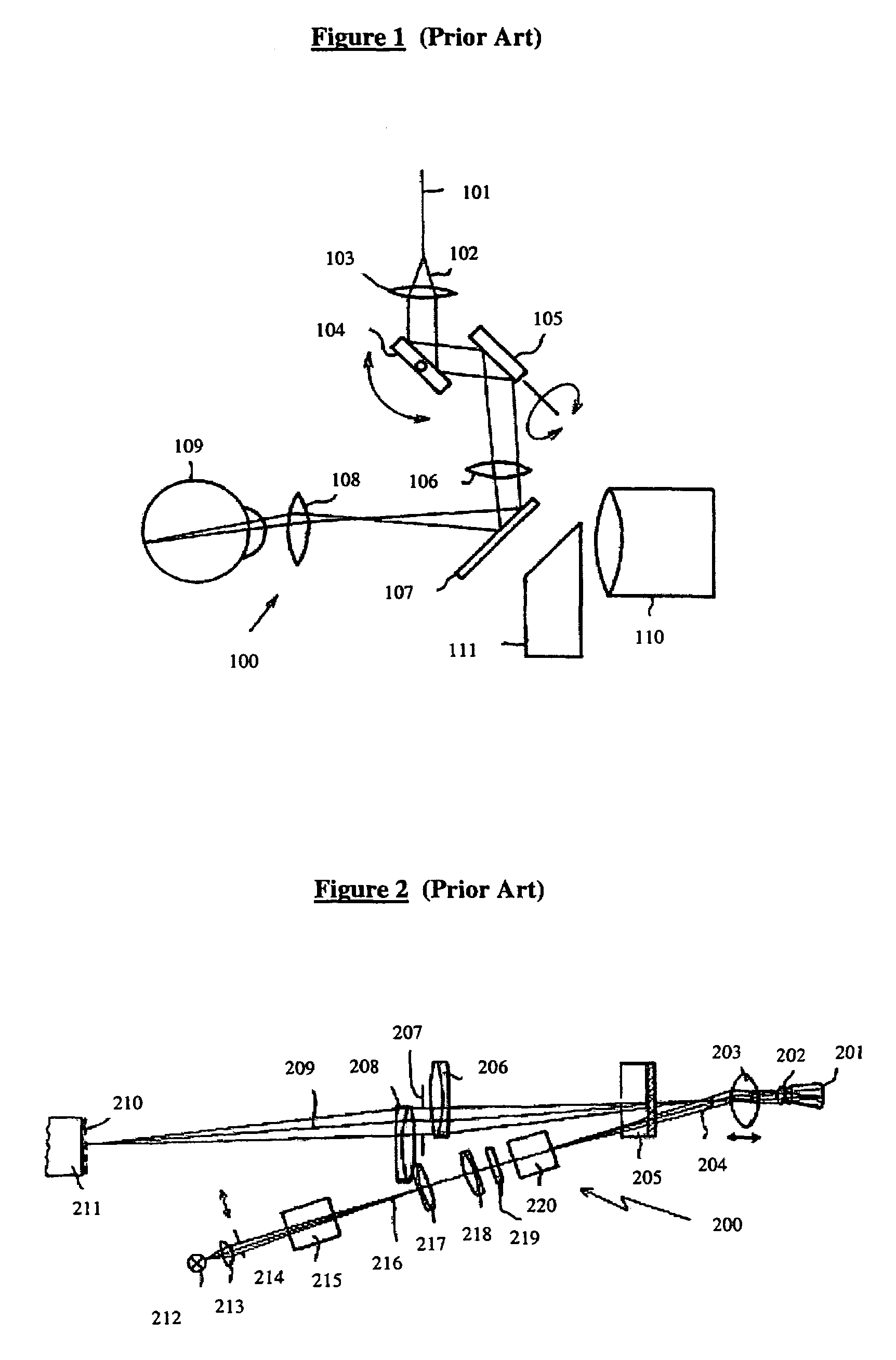
[0023]FIG. 1 illustrates an OCT scan unit 100 that was described in U.S. Pat. No. 5,537,162, “Method and Apparatus for Optical Coherence Tomographic Fundus Imaging Without Vignetting,” issued on Jul. 16, 1996. As shown in FIG. 1, light from optical fiber 101 is collimated by lens 103 and coupled into paired galvanometers 104 and 105. Together, galvanometers 104 and 105 can scan beam 102 from optical fiber 101 in two orthogonal directions, which allows scanning in any arbitrary pattern ...


PUM


Abstract

An eye examination instrument is presented that can perform multiple eye tests. The instrument includes an illumination optical path and an imaging optical path, wherein a focus element in the illumination optical path is mechanically coupled to a focus element in the imaging optical path. In some embodiments, the eye examination instrument can perform a visual eye test, a fundus imaging test, and an optical coherence tomography test.

Description

[0001]This disclosure claims priority to U.S. Provisional App. No. 60 / 626,357 filed on Nov. 8, 2004, by Jay Wei and Yonghua Zhao, which is herein incorporated by reference in its entirety.BACKGROUND[0002]1. Field of the Invention[0003]This invention is related to optical inspection instrumentation and, in particular, to an apparatus and method that can be utilized in comprehensive eye diagnosis.[0004]2. Discussion of Related Art[0005]Visual field testing is a conventional clinical method utilized in the diagnosis of eye diseases that cause degradation of vision sensitivity. One of the most accepted methods utilized in the diagnosis of such diseases is the Standard Automated Perimeter (SAP) test, which tests brightness contrast sensitivity over a large visual field. There are many instruments for performing an SAP test routinely used in clinics including, for example, those produced by Carl Zeiss Meditec (Dublin, Calif.).[0006]Typically, visual field testing utilizes functional field...

Claims


Application Information

Patent Timeline
28 Nov 2006
Publication
US7140730B2
IPC
A61B3/13; G01B9/02
CPC
A61B3/14; A61B3/1025; A61B3/156
Inventors
WEI, JAY; ZHAO, YONGHUA