Roll on/roll off ramp-deck transport platform

a technology for transporting platforms and ramps, applied in the field of transport platforms, can solve the problems of reducing limiting the utility of the platform and the number of platforms, and the thickness of the platform and the deck is relatively larg

Inactive Publication Date: 2006-11-28
ITL TECH
View PDF28 Cites 14 Cited by
  • Summary
  • Abstract
  • Description
  • Claims
  • Application Information

AI Technical Summary

Benefits of technology

[0014]It is within the scope of this aspect of the invention to have a second downwardly angled and sloped portion at a second end of the platform to produce a second end-edge at the second end of the platform which also a vertical height that allows vehicles to roll from a surface on which the platform is disposed, against and up over the second end-edge, and onto the deck without the interposition of structures movable with respect to the deck.

Problems solved by technology

That is to say, due to the limited ability of the platforms to bear large vertically acting loads such as those generated by the placement of a fully laden container on top thereof, the platforms have had to be disposed at the very tops of the container stacks.
This, of course, severely limits both their utility and the number of platforms which can be carried on any one vessel.
A further drawback that open transport platforms suffer from is that, in order to have sufficient structural strength and durability, the platform and deck are relatively thick.
This, of course, reduces the utility of the platform in that additional / ancillary equipment which is in itself heavy must either be carried with the platform, adding to its dead weight and complexity, or alternatively some means for moving the ancillary equipment about, such as fork lift of the like, must also be provided at both the site where the vehicles are loaded and the site wherein the vehicles are unloaded.
In the case of a military operation (for example), it is often such that conditions are less than favorable and in the case of war or the like, the availability of ramps and fork lifts cannot be guaranteed and the daunting task of manually moving such heavy pieces of equipment from platform to platform may be too much should sufficient man-power (for example) not be available.
In addition to the above shortcoming, open transport platforms have suffered from the drawback that the holds of modern container ships are usually constructed to receive predetermined sized containers which are usually 40′×8′ long ISO (International Standards Organization) containers.
However, it has been extremely difficult, if not impossible, to dispose anything but the 40′×8′ ISO containers in the holds, and attempts to dispose transport platforms below deck have not met with success.
Thus, storage in such holds has been limited to the above mentioned 40′×8′ ISO containers which are dimensioned to fit in the cell guides.
This means that off-sized containers or platforms, which are either wider or narrower than the width of the cell guides, cannot be secured below deck in the holds and are relegated to possible disposition above deck.

Method used


Image

  • Roll on/roll off ramp-deck transport platform
  • Roll on/roll off ramp-deck transport platform
  • Roll on/roll off ramp-deck transport platform

Examples


first embodiment

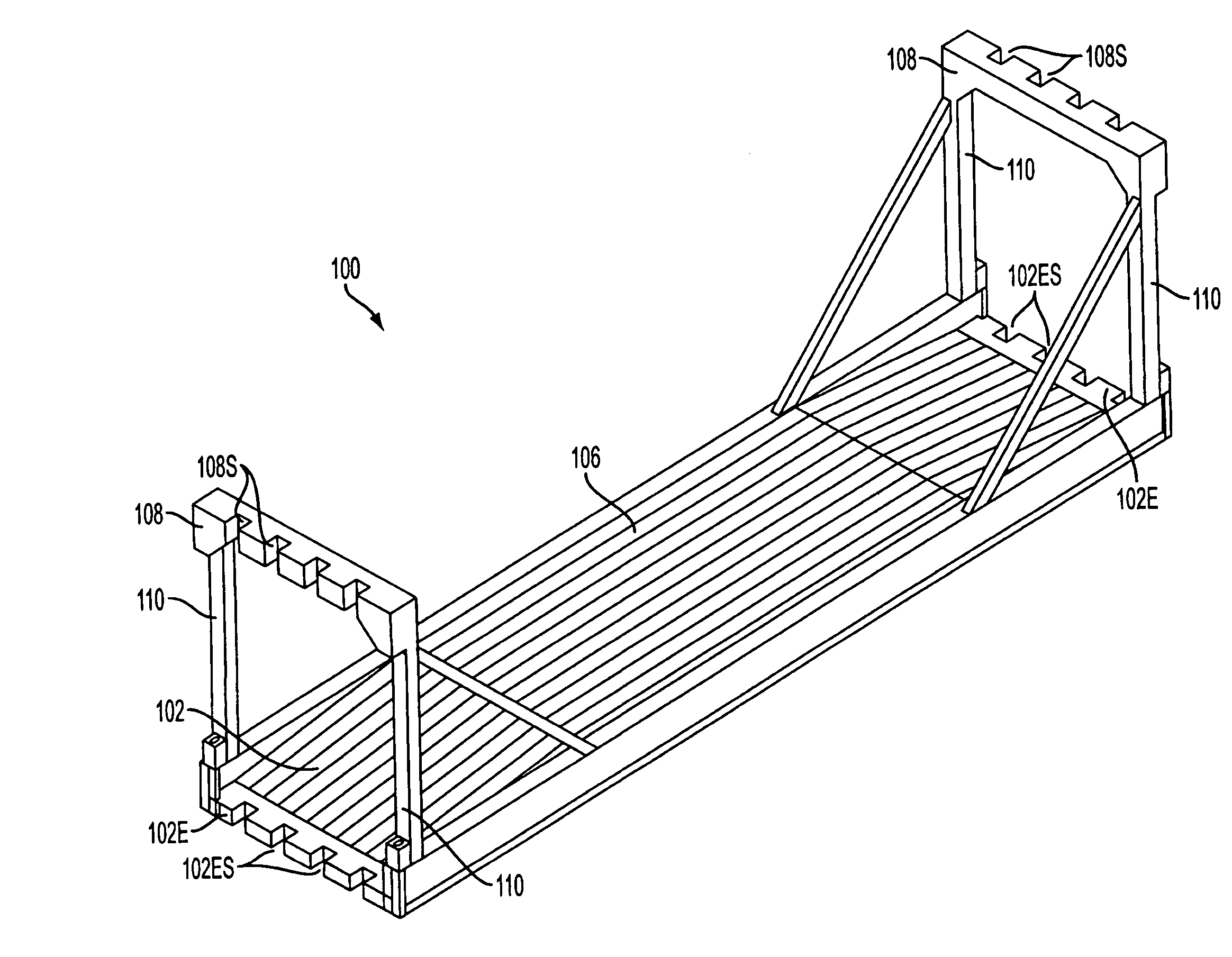
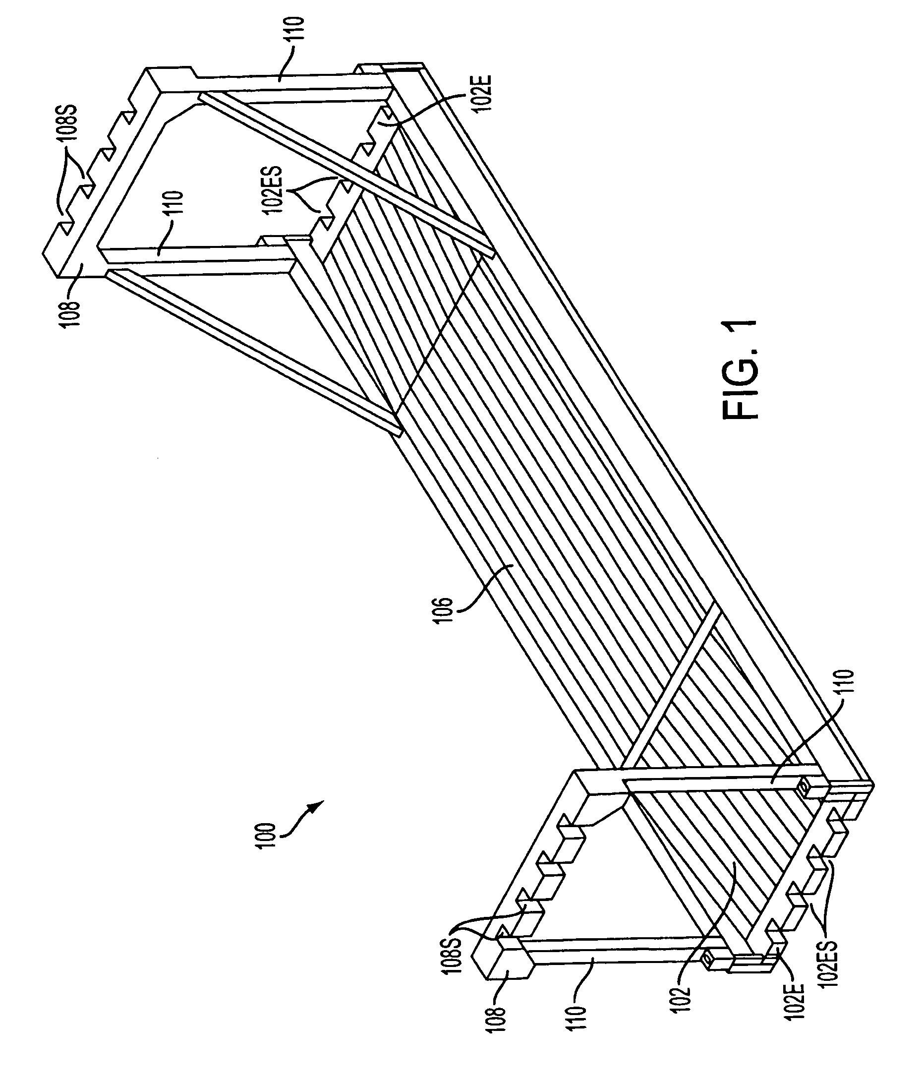
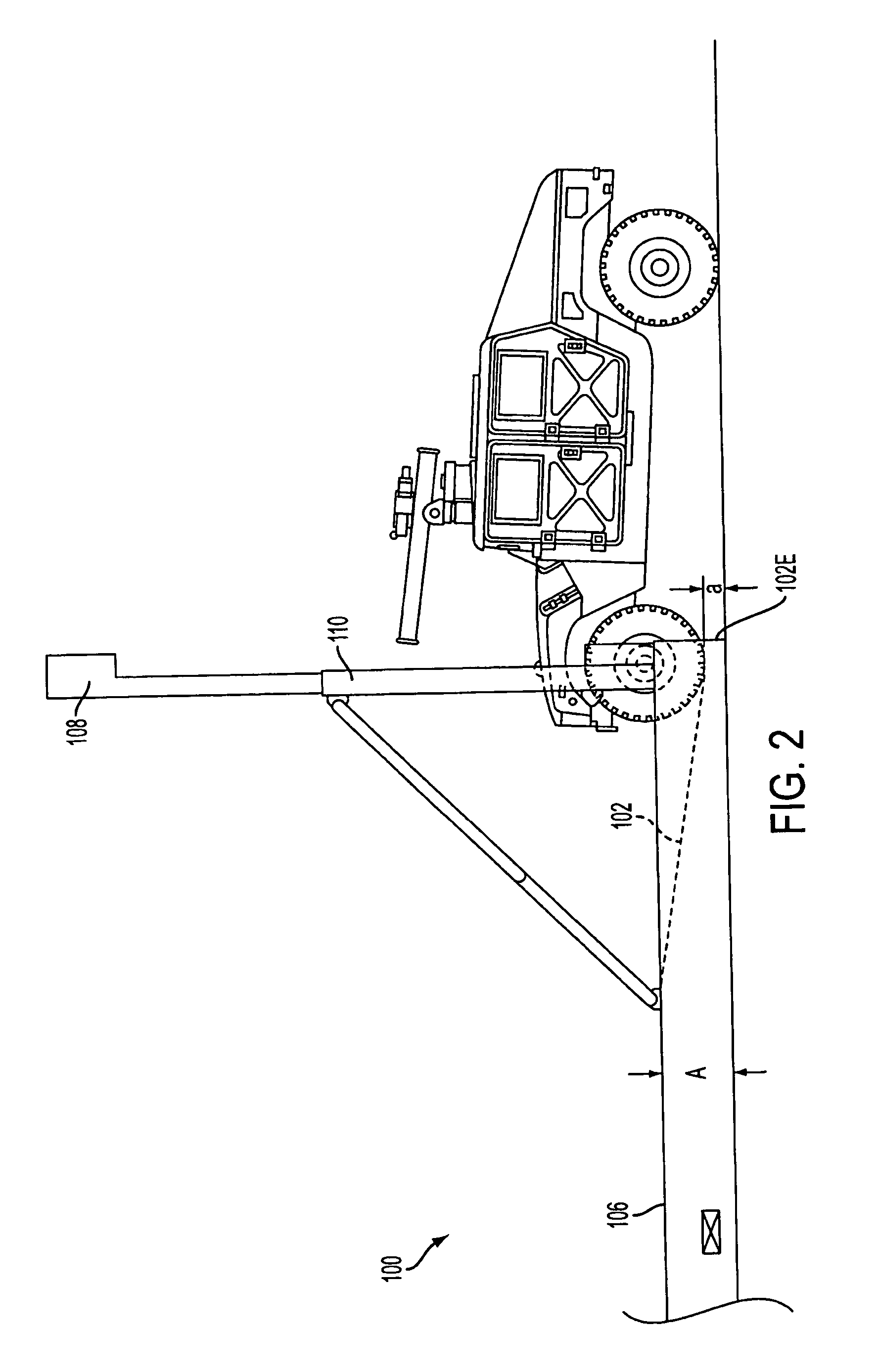
[0037]FIG. 1 is a perspective view of an easy roll on / roll off ramp-deck transport platform 100 according to the invention. This platform 100 is constructed so that both of the two opposed end portions 102 of the platform 100 are sloped and lead from an essentially flat, horizontal central portion 106 to each end of the platform. This sloping deck construction reduces the vertical height of the edges 102E of the platform from “A” to “a” in the manner depicted in FIG. 2.

[0038]This reduction in vertical height (A→a), wherein “A”, by way of example only, can be about 24″ and “a” can be about 6″, renders the edges 102E of the platform 100 readily traversable by wheeled vehicles in the manner illustrated in FIG. 2 Hence, with no moving parts or the need for additional structures such as ramps and the like, medium sized wheeled / track vehicles such as SUV (Sports Utility Vehicles) and even smaller vehicles (wheeled or tracked vehicles) are able to drive up and onto the platform with relati...

second embodiment

[0042]FIG. 5, in this instance is such as to show a stack of 40′ ISO containers C4 (note that two 20′ containers can be placed end to end in place of a 40′ container); four stacks of transport platforms TPS (TPS-1 . . . TPS-4) according to the invention; and a further stack of ISO containers C5, which are disposed in a hold HLD in the illustrated manner. The bulkhead B / H is shown as having a plurality of vertically extending T-guide members T / G rigidly connected thereto. Cell guides Cg1, Cg2, Cg3 . . . Cgn in which ISO containers can be slidably disposed, are defined between each adjacent two of the T-guide members T / G. Empty cell guides Cg8, Cg9 are shown at a right hand side of the figure.

[0043]The slots 102ES and 108S are aligned with one another and spaced in a predetermined relationship with the distance between the T-guides T / G. The width of the slots is selected to allow for ship-to-ship variations in the dimensions of the T-guide members T / G and are such as to leave a small ...

third embodiment

[0056]Support blocks 360 are provided on either the deck or the masts to engage the mast when it is in a folded position and extends essentially parallel to the top of the deck. Further, the deck and mast are provided with projections 362, 363 which in this embodiment are essentially triangular in shape. These projections 362, 362 are use to connect the ends of an angled braces (not shown in this figure) which establish a reinforcing triangulation. In this third embodiment, these angle braces maintain the masts upright during use.

[0057]These projections 363 can also be used as connection sites for tie-down cables / chains if so required.

[0058]The hinges 365 in this third embodiment are constructed so that the pivot shaft is a bolt which can be removed to allow the mast be disconnected / replaced or the like.

[0059]As shown in FIG. 19, further outwardly extending projections 367 are provided on the masts. These projections 367 are slotted and are arranged so that the slots align with one ...


PUM


Abstract

A transport platform structure which is configured for vehicle roll on / roll off has a deck having a downwardly angled sloped portion at at least one end to produce an end-edge at an end of the platform. This end edge is dimensioned to have a vertical height configured to allow wheeled vehicles to roll from a surface on which the platform is disposed, against and up over the end-edge, and onto the deck without the interposition of structures movable with respect to the deck.

Description

CROSS-REFERENCE TO RELATED APPLICATIONS[0001]The present application is a continuation-in-part of a U.S. patent application Ser. No. 10 / 622,536 filed on Jul. 21, 2003 now U.S. Pat. No. 7,011,479 in the name of Bernard S. Sain, the entire contents of which are hereby incorporated by reference.BACKGROUND OF THE INVENTION[0002]1. Field of the Invention[0003]The present invention relates generally to transport platforms for transporting cargo on container ships, and more specifically to open transport platforms which are configured for transporting oversized cargo such as vehicles / equipment and the like that cannot fit onto currently available transport platforms, and which are configured to permit vehicles to roll on and off without the need of additional structures such as ramps and the like.[0004]2. Description of the Related Art[0005]Open transport platforms, which have been used to transport vehicles or the like, have usually, due to their configuration and limited structural stren...

Claims


Application Information

Patent Timeline
Patent Type & Authority Patents(United States)
IPC IPC(8): B60P7/06B65D88/00B65D88/12
CPCB65D88/005B65D88/129B65D2585/686
Inventor SAIN, BERNARD S.
Owner ITL TECH
Why Eureka
Try Eureka