
Orthodontic bracket with reinforced tiewings

a tiewing and orthodontic technology, applied in the field of orthodontic brackets, can solve the problems of affecting affecting the aesthetic appearance of the tooth, and affecting the progress of treatment, so as to reduce the likelihood of tiewing fracture, improve aesthetic appearance, and reduce the overall size of the bracket

Active Publication Date: 2006-11-28
3M INNOVATIVE PROPERTIES CO
View PDF42 Cites 52 Cited by
  • Summary
  • Abstract
  • Description
  • Claims
  • Application Information

AI Technical Summary

Benefits of technology

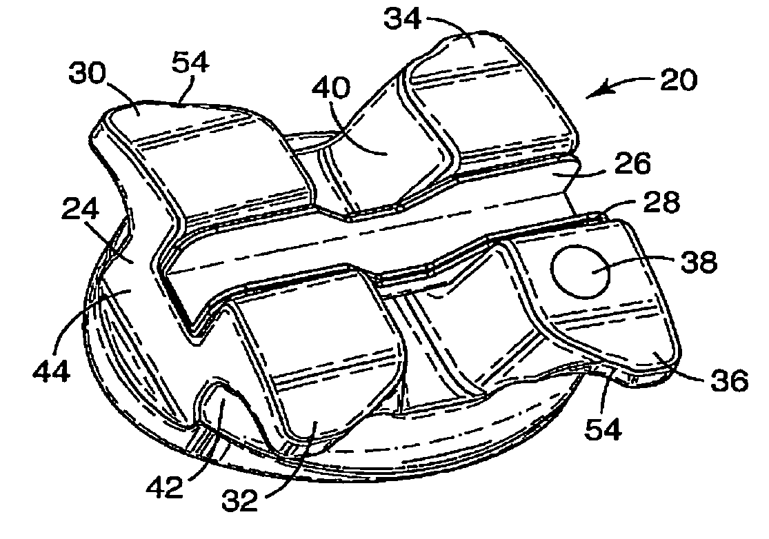
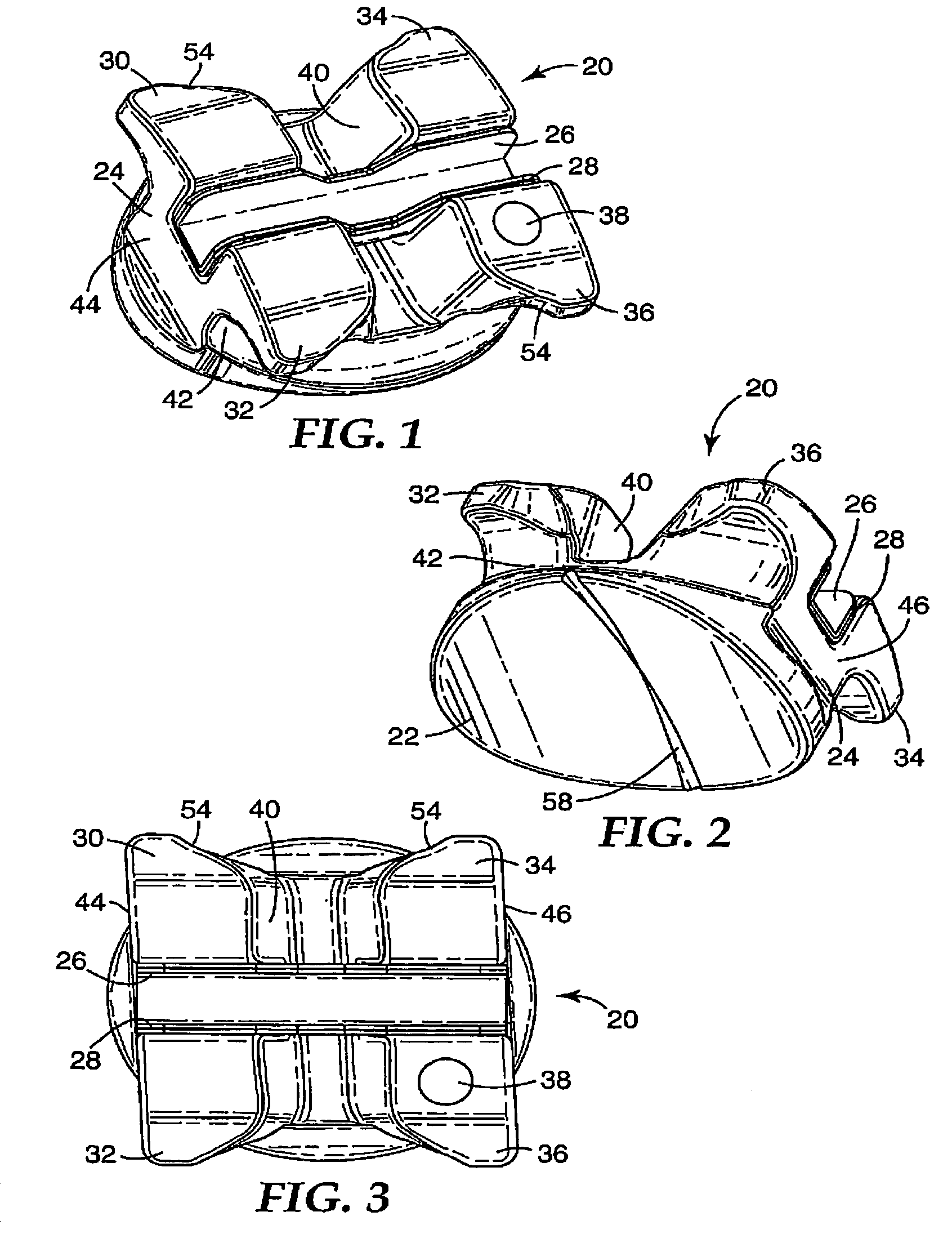
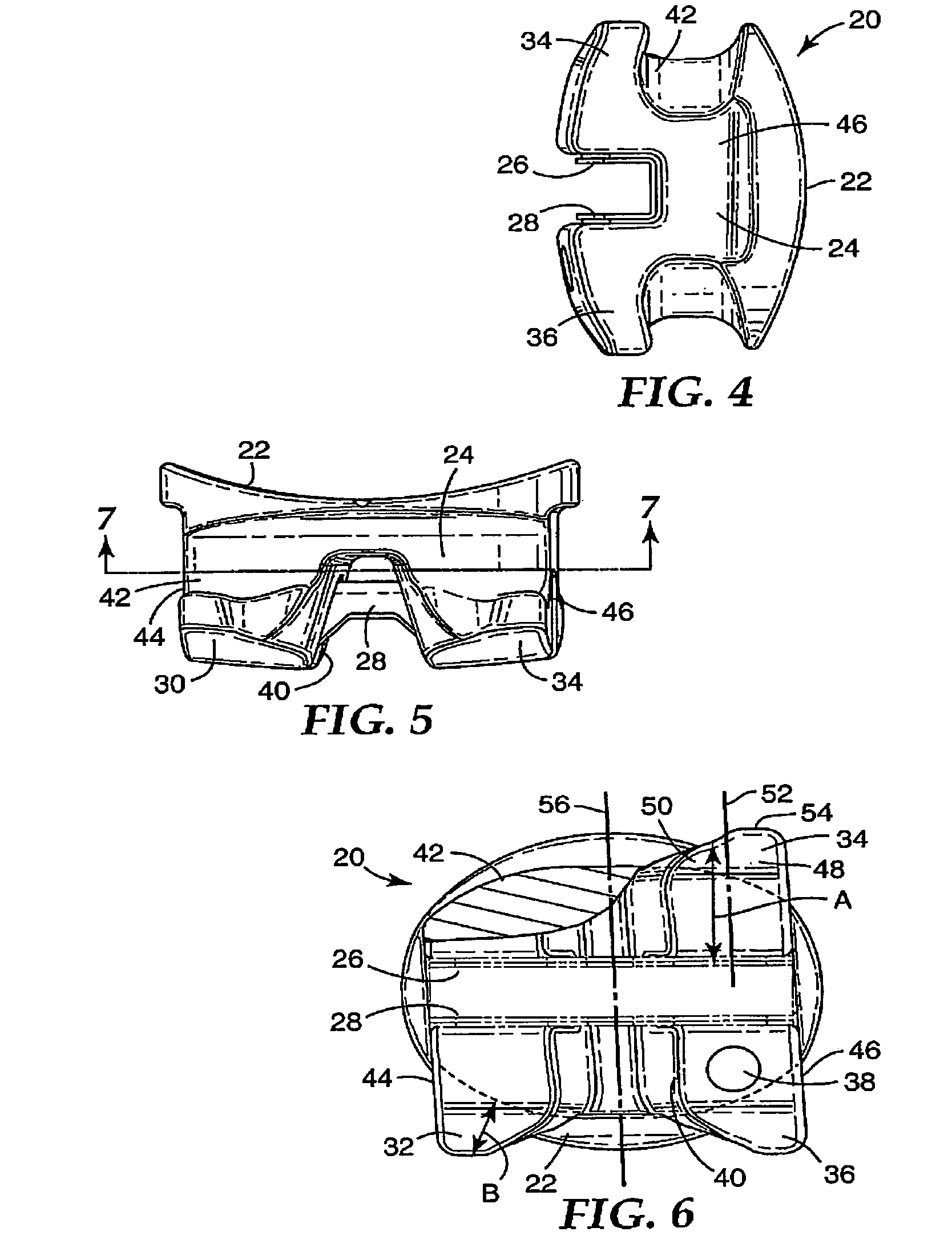
[0012]The present invention is directed to an orthodontic bracket having one or more tiewings that are constructed to reduce the likelihood of tiewing fracture during treatment while securely retaining the ligature in place. The tiewings are reinforced by constructing the bracket in such a manner that the bracket material is gradually added along the ligature groove as the inner side of the tiewing or the center of the bracket is approached. This construction enables the overall size of the bracket to be significantly reduced, resulting in a bracket having an improved aesthetic appearance.

Problems solved by technology

However, attempts to reduce the overall size of the bracket are often hampered at least in part by the tiewings, since the tiewings should extend outwardly a distance sufficient to reliably retain the ligature in place.
If the ligature is accidentally dislodged from its position behind the tiewings, the archwire may release from the bracket with the result that the progress of treatment is interrupted.
However, ceramic materials are relatively brittle and lack strength in tension.
If the tiewings of ceramic brackets are too small, they may fracture when exposed to unexpectedly large forces during the course of treatment.

Method used


Image

  • Orthodontic bracket with reinforced tiewings
  • Orthodontic bracket with reinforced tiewings
  • Orthodontic bracket with reinforced tiewings

Examples


Embodiment Construction

[0027]As used herein, “mesial” refers to a direction toward the middle of the patient's arch and “distal” refers to a direction away from the middle of the patient's arch. “Occlusal” refers to a direction toward the outer tips of the patient's teeth, while “gingival” refers to a direction toward the gums or gingiva. “Labial” refers to a direction toward the patient's lips or cheeks, while “lingual” refers to a direction toward the patient's tongue. A “facial plane” means a reference plane perpendicular to a reference axis extending in a labial-lingual direction.

[0028]An orthodontic bracket according to one embodiment of the invention is illustrated in FIGS. 1–7 and is broadly designated by the numeral 20. The bracket has a base 22 adapted for directly bonding to the enamel surface of a patient's tooth. Preferably, the base 22 has a compound concave contour that matches the compound convex contour of the patient's tooth surface.

[0029]Optionally, the base 22 is provided with a means f...


PUM


Abstract

An orthodontic bracket has at least one tiewing and a groove behind the tiewing for receiving a ligature. The groove extends along a path that is inclined in a direction away from an archwire slot of the bracket as a central, upright reference plane bisecting the bracket is approached. In addition, the depth of the groove decreases as the reference plane is approached. Preferably, an outermost edge of at least one tiewing is inclined in a direction away from the archwire slot as the adjacent side of the bracket is approached. The tiewing is less likely to fracture during the course of orthodontic treatment, and yet the ease of ligation is not compromised.

Description

BACKGROUND OF THE INVENTION[0001]1. Field of the Invention[0002]This invention broadly relates to an appliance used in the course of orthodontic treatment to correct a malocclusion. More particularly, the present invention relates to an orthodontic bracket having at least one tiewing for ligating an archwire to the bracket.[0003]2. Description of the Related Art[0004]Orthodontic treatment involves movement of a patient's teeth to improved positions. Orthodontic treatment can improve the patient's occlusion, so that the teeth function better with each other during mastication. Orthodontic treatment can also greatly enhance a patient's facial appearance, especially in instances where the teeth adjacent the front of the oral cavity are noticeably crooked.[0005]One type of orthodontic treatment system includes a set of tiny appliances known as brackets that are fixed to the patient's anterior, cuspid and bicuspid teeth. Each of the brackets has a slot to receive a resilient wire known a...

Claims


Application Information

Patent Timeline
Patent Type & Authority Patents(United States)
IPC IPC(8): A61C3/00A61C7/14
CPCA61C7/14
Inventor LAI, MING-LAIPOSPISIL, JIRINA V.
Owner 3M INNOVATIVE PROPERTIES CO
Learn More