Surgical intramedullary implant with improved locking for fixation of fractured bone segments

a technology of intramedullary implants and fractured bone, which is applied in the field of surgical intramedullary implants with improved locking for can solve the problems of limiting the reamed diameter, difficult to insert distal locking screws, and general abandonment of distal locking jigs b>500/b>, and achieves the effect of simplifying the fixation of fractured bone segments

Active Publication Date: 2006-11-28
MANDERSON EASTON L
View PDF5 Cites 17 Cited by
  • Summary
  • Abstract
  • Description
  • Claims
  • Application Information

AI Technical Summary

Benefits of technology

[0018]It is an objective of the present invention to simplify the fixation of fractured bone segments.
[0021]The intramedullary nail is inserted into the cavities by the surgeon. When fully inserted, the nail extends from the expanded cavity to the distal end of the primary cavity. With the intramedullary nail inserted, a bone fragment covering the first hole is removed from the proximal area of the fractured bone. The removal of this bone fragment makes the first hole visible to the naked eye of the surgeon, and therefore facilitates the insertion of the proximal locking screw, as will be discussed further below.

Problems solved by technology

For each individual patient there are limitations on the reamed diameter due to the constraints of the cortical surfaces.
Variations in position of a millimeter or more can make it very difficult to insert distal locking screws.
Therefore, in practice, distal locking jigs 500 have generally been abandoned because of the great difficulty experienced in successfully in placing distal locking screws using a jig technique.
This is very difficult to do and exposes the surgeon, who may be required to perform the freehand technique a number of times each month or year, to dangerous levels of radiation.
Needless to say, the fluoroscopy machine 520 has to stay positioned throughout the procedure, because even after drilling it can be difficult to find the weight bearing drilled nail hole 312.
In the vast majority of the cases, if only one distal screw is used it will break, making the bone more susceptible to infection and making removal of the screw fragments almost impossible.

Method used


Image

  • Surgical intramedullary implant with improved locking for fixation of fractured bone segments
  • Surgical intramedullary implant with improved locking for fixation of fractured bone segments
  • Surgical intramedullary implant with improved locking for fixation of fractured bone segments

Examples


Embodiment Construction

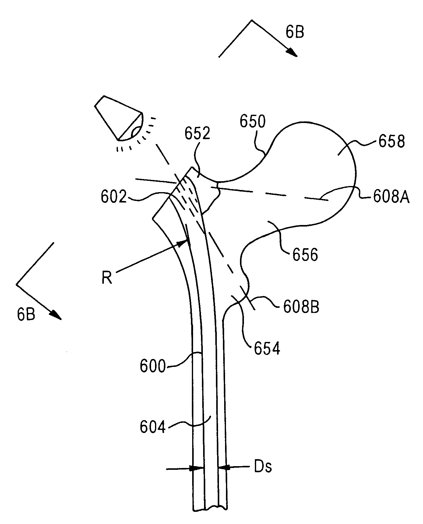
[0063]In accordance with the invention, and except as otherwise described below, the preparation of the patient and the surgical incision are performed as described previously. A starting hole, as in conventional techniques, will be made in the greater trochanter, and a guide wire will be inserted through the greater trochanter, and into the intermedullary canal, stopping at the predetermined end of the distal femur. Once the wire has been seated properly, as confirmed by a fluoroscopy machine, reaming of the proximal end of the femur in the trochanter area will be performed with different size reamers. The proximal end of the greater trochanter can be reamed up to 17 millimeters. This size will vary depending upon the individual patient. That is, the reaming will be customized to accommodate the varied anatomy of individual patients.

[0064]Referring now to FIGS. 6A–6E′, the nail 600 has a proximal end 602, with a diameter Dp which is larger by 2, 3 or 4 millimeters, or even more, th...


PUM


Abstract

To set a fractured bone using an intramedullary nail having a hole for a proximal locking screw, the surgeon reams a primary cavity extending from a proximal area, across a fractured area, and into a distal area of the fractured bone, to a first diameter. An expanded cavity is also reamed in the proximal area of the fractured bone. The reamed primary and expanded cavities are aligned. The intramedullary nail is inserted so as to extend from the expanded cavity to a distal end of the primary cavity. With the intramedullary nail inserted, a bone fragment in the proximal area of the fractured bone, which covers the hole, is removed. The proximal locking screw is inserted through the uncovered hole and into the proximal area of the fractured bone without the use of a jig. The removed bone fragment is then secured back onto to the proximal area of the fractured bone from which it was removed, after insertion of the screw.

Description

TECHNICAL FIELD[0001]The present invention relates to surgical intramedullary implants for setting bone fractures, and more particularly to a surgical intramedullary implant with improved locking for fixation of fractured bone segments.BACKGROUND OF THE INVENTION[0002]The conventional method of intramedullary nailing of a fractured or broken femur, as shown in FIG. 1A, requires first placing the patient 100 on the fracture table 110 for the surgical treatment e.g., intramedullary nailing of a left femur. The patient is shown to be in a supine position, that is, lying on his / her back. The feet are placed in a traction device 120 which holds the femur stretched out to length. In the majority of cases, this will be sufficient to allow the surgical procedure to proceed. FIG. 1B shows a frontal projection of the patient 100 in the supine position.[0003]The position of the broken fragments is monitored by an x-ray machine called a “fluoroscopy machine” (not shown) which provides real-time...

Claims


Application Information

Patent Timeline
Patent Type & Authority Patents(United States)
IPC IPC(8): A61B17/58A61B17/16A61B17/17A61B17/22A61B17/56A61B17/72A61B17/86A61B17/92A61B19/00
CPCA61B17/72A61B17/1604A61B17/1725A61B17/7283A61B17/86A61B17/921A61B2017/1602A61B2017/22038A61B2019/461A61B2090/061
Inventor MANDERSON, EASTON L.
Owner MANDERSON EASTON L
Why Eureka
Try Eureka