Intelligent power distribution system

a power distribution system and intelligent technology, applied in the direction of relays, liquid/fluent solid measurements, instruments, etc., can solve the problems of computer failure to initialize when the computer subsequently receives, hard failure of monitors, and excessive stress on oscillators, so as to reduce the tripping of branch circuit breaker.

Inactive Publication Date: 2006-11-28
AMERICA POWER CONVERSION CORP
View PDF8 Cites 211 Cited by
  • Summary
  • Abstract
  • Description
  • Claims
  • Application Information

AI Technical Summary

Benefits of technology

[0009]It is an object of the present invention to provide an intelligent power distribution system and method for using the power distribution system. In embodiments of the present invention, the intelligent power distribution system can manage power consumption to minimize tripping of a branch circuit breaker which provides electrical power to the system.

Problems solved by technology

Allowing the oscillators to operate in an unsynchronized condition can result in undue stress to the oscillators and hard failure of the monitor.
Otherwise, the printer can potentially back-feed power or control signals to the computer and cause the computer to fail to initialize when the computer subsequently receives power.
This method is generally unsatisfactory, because the time delay interval is difficult to control and duplicate manually, and further, because it may be desirable to ensure that the power up and power down of the system always occur according to a particular sequence.
This method is also unsatisfactory, as well as being very expensive.
Furthermore, the power up delay is typically equal to the power down delay, a condition which may be undesirable in certain cases.
Finally, the time delay provided by the TDRs is typically not easy to adjust by an operator.

Method used


Image

  • Intelligent power distribution system
  • Intelligent power distribution system
  • Intelligent power distribution system

Examples


Embodiment Construction

[0036]In the following detailed description of the present invention numerous specific details are set forth in order to provide a thorough understanding of the present invention. However, it will be obvious to one skilled in the art that the present invention may be practiced without these specific details. In other instances, well known methods, procedures, components, and circuits have not been described in detail as not to unnecessarily obscure aspects of the present invention.

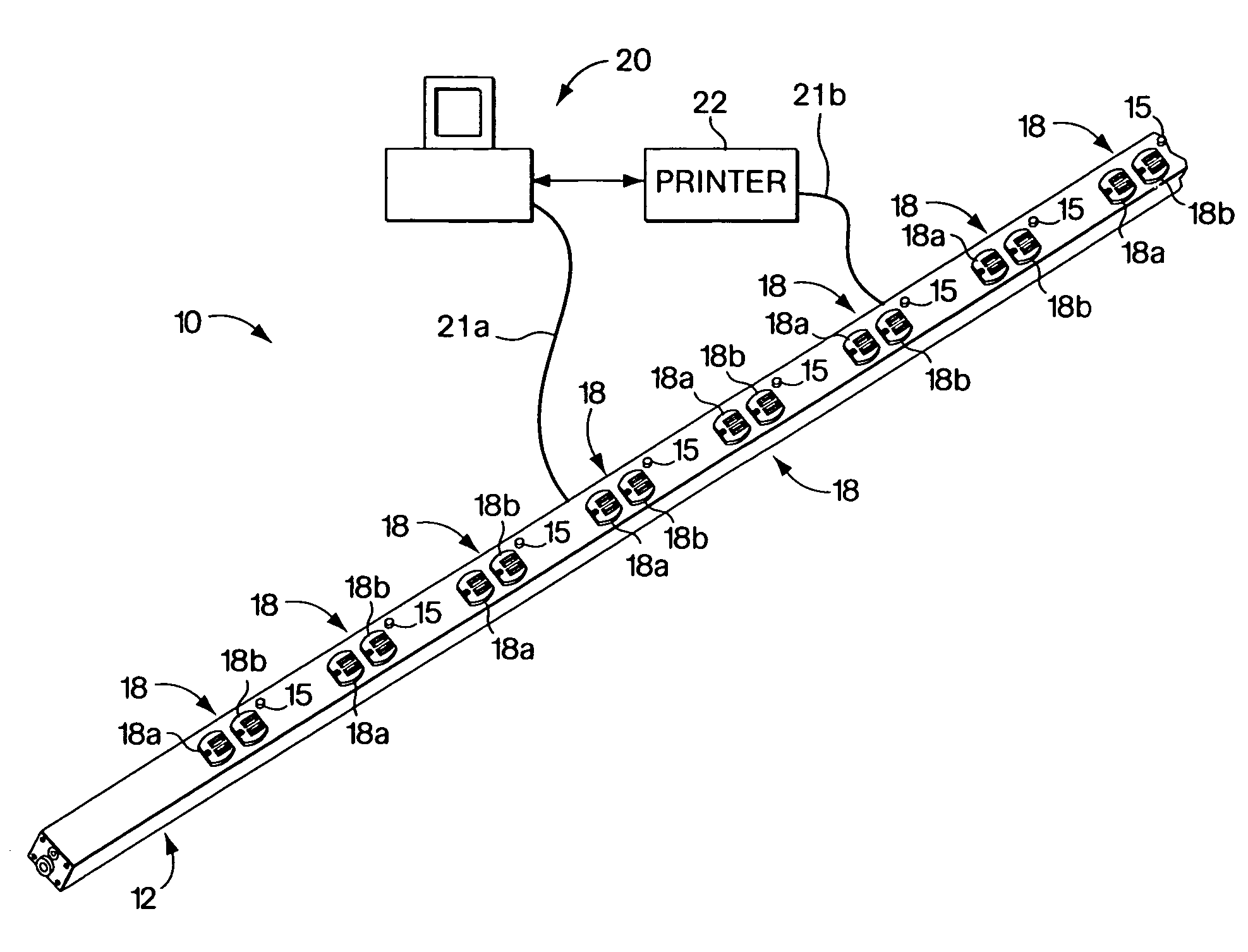
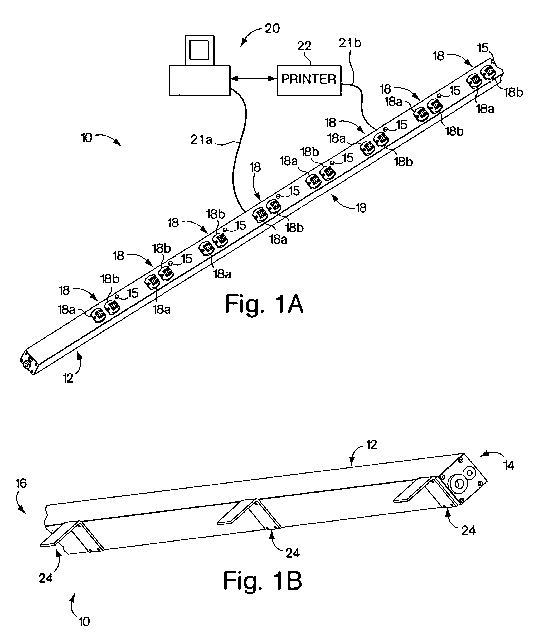
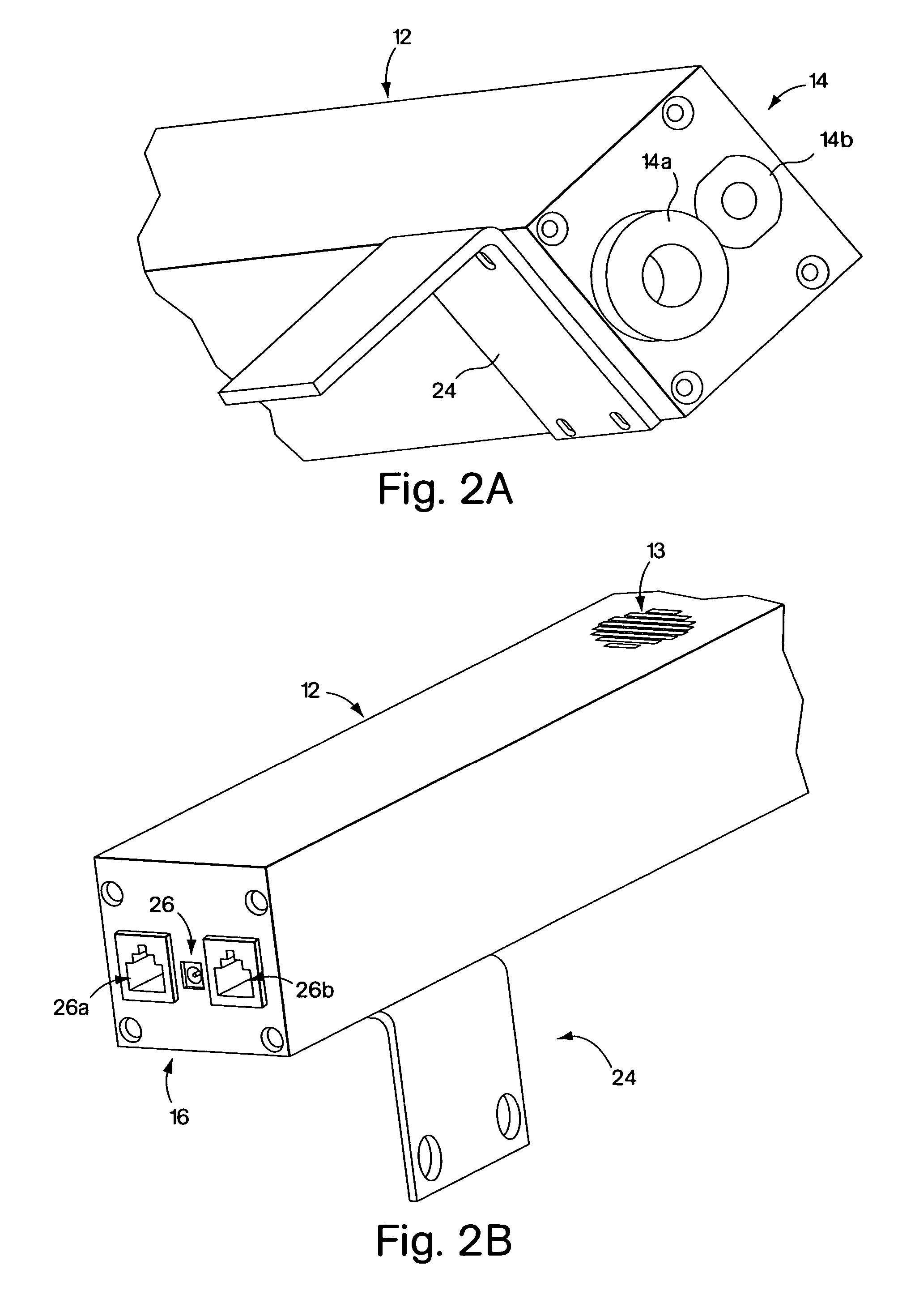
[0037]In accordance with an embodiment of the present invention, an intelligent power strip is set forth that can provide electrical power and power management to one or more computer systems and their related peripheral devices. The power strip includes internal power management circuitry and external power outlets. The intelligent power strip can operate in conjunction with power management procedures, within the scope of the present invention, to provide a power management system for conventional comput...


PUM


Abstract

An intelligent power distribution system including one or more intelligent power strips. The power strips can each include an elongated housing that may be adapted for mounting in an equipment rack. The housing can include a first end, a second end and plurality of power outlets mounted thereon. The first end can have a number of apertures that enable power and signal conductors to enter an interior region of the housing. The second end can include a first and a second communication port. The first communication port may be adapted to enable a computer to communicate with the power the strip. The second communication port may be adapted to enable the power the strip to be daisy chained with a second intelligent power strip. The power strip further includes power management circuitry that can power-on and power-off the power outlets in accordance with an operator defined sequence and delays. The power management circuitry can further sense electrical current drawn by the power strip and control operation of the power strip based on the sensed electrical current to minimize branch circuit breaker tripping.

Description

RELATED APPLICATIONS[0001]This application is a continuation of U.S. patent application Ser. No. 09 / 688,298, now U.S. Pat. No. 6,741,442, filed Oct. 13, 2000 and entitled, “Intelligent Power Distribution System,” the disclosure of which is herein incorporated by reference.FIELD OF THE INVENTION[0002]The present invention generally relates to an intelligent power distribution system and method, and more particularly to an intelligent power strip and method of distributing power in an electronic system.BACKGROUND[0003]Many electronic and electrical systems, such as computer and home entertainment systems, require that electrical power be applied to components of the system according to a particular sequence to avoid causing undue stress and possible damage to the components. Particularly with computer systems, there are many situations in which it is advantageous to delay activation of peripheral devices until after the parent device is powered up and has attained a quiescent state. A...

Claims


Application Information

Patent Timeline
Patent Type & Authority Patents(United States)
IPC IPC(8): H02J1/00G06F1/20G06F1/26H02J1/14H05K7/14
CPCG06F1/206G06F1/266H05K7/1457G06F2200/261H02J1/14Y02B60/1275Y02B60/1296Y02D10/00
Inventor MCNALLY, JOHNROHR, DANIEL
Owner AMERICA POWER CONVERSION CORP
Why Eureka
Try Eureka