Transformer with housing and switch gear

a transformer and switch gear technology, applied in the direction of transformer/inductance casing, switch details, air-break switch, etc., to achieve the effect of small equipment footprint, small overall dimension, and small equipment footprin

Active Publication Date: 2006-11-28
CARTE INT
View PDF6 Cites 26 Cited by
  • Summary
  • Abstract
  • Description
  • Claims
  • Application Information

AI Technical Summary

Benefits of technology

[0035]The transformer disclosed herein is the next generation of Primary Service Entrance Transformers (PSET Transformers). The product incorporates the most fundamental requirements of the PSET package design into a new transformer product which improves the functionality while significantly reducing the overall size of the equipment. The product design uses available components to create a transformer package retaining the switching capabilities and operating practices common to the PSET. The product is completely tamperproof, meeting or exceeding established standards and requirements for enclosure integrity of pad mounted transformers.
[0041]The most salient feature of the transformer disclosed herein is the use of a 3-phase under oil load break switch in a manner in which the switch contacts are visible (as shown below). A viewing window allows the user / operator full visibility of the oil-immersed switch contacts.
[0044]The load break switch is preferably modified to provide an interlocked switch index plate, which enhances the safety aspects of the equipment package. There are two key interlocks that are used to establish very clear and safe operating conditions. The index plate of the load break switch and the low voltage door both feature key interlocks.
[0045]The load break switch index plate is preferably designed in such a way that the key from the load break switch interlock can not be removed unless the load break switch is in the de-energized position. This is a Type F interlock. The second interlock is incorporated into the low voltage door and flip-top cover of the cabinet design. The second interlock is a Type D interlock. In order to open the second interlock (on the low voltage door), the key from the first interlock (on the load break switch) must be removed. By having the interlocks share the same key in this manner ensures that the low voltage door and flip-top of the cabinet can not be opened unless the primary load break switch is in the de-energized position.
[0049]One of the key advantages which can be obtained is a significantly smaller overall dimensions and smaller equipment footprint. In one example, the product may be 89″ deep (including the radiators)×71″ high×81″ wide. A smaller footprint for the equipment will mean that a smaller mounting pad is required versus a PSET transformer; this will translate into lower installation costs.

Problems solved by technology

Submersible products are often used only in high density load centers where there is insufficient real estate for pad mounted transformer installation.
Very large loads require the use of medium power or large power transformers.

Method used


Image

  • Transformer with housing and switch gear
  • Transformer with housing and switch gear
  • Transformer with housing and switch gear

Examples


Embodiment Construction

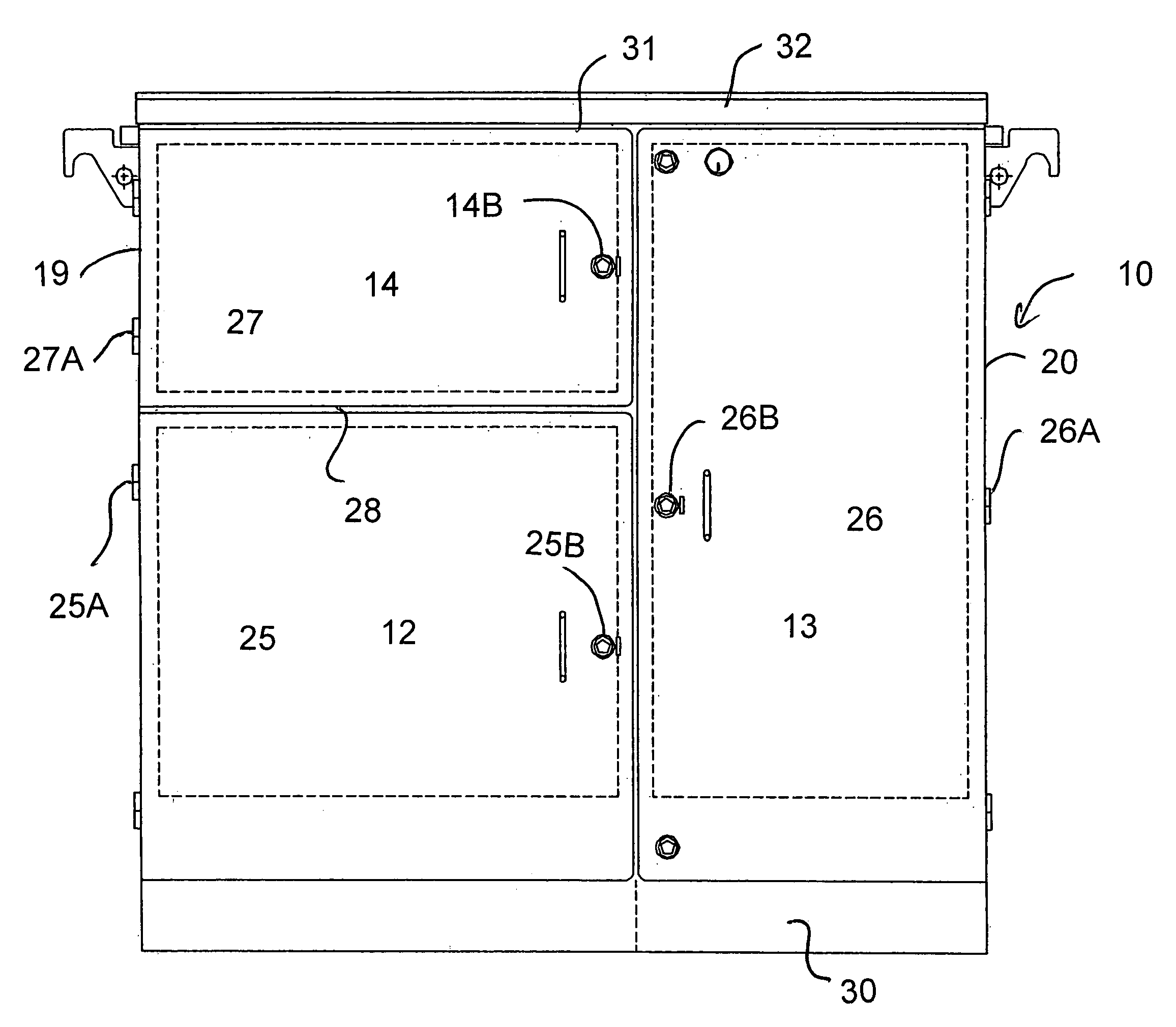
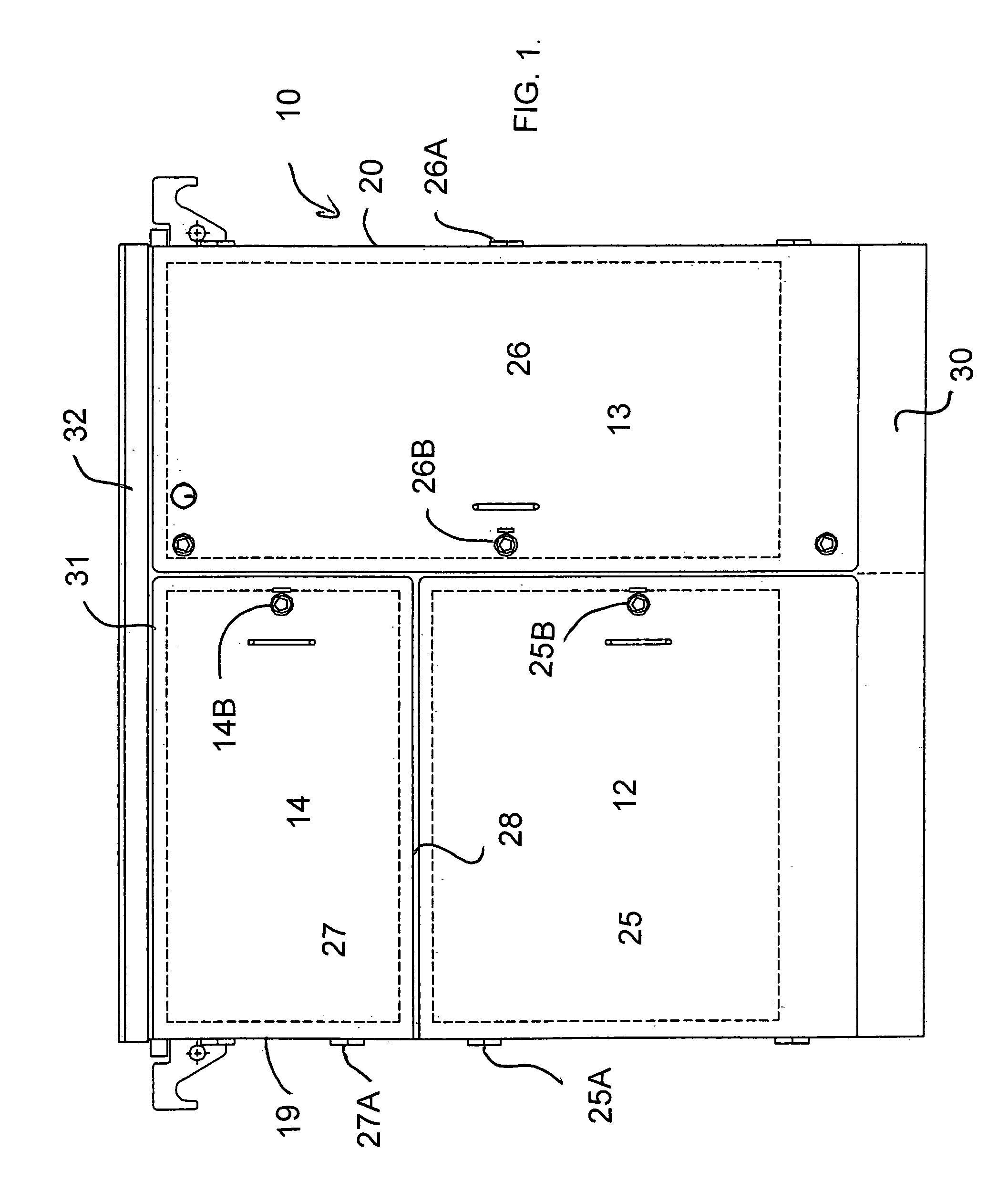
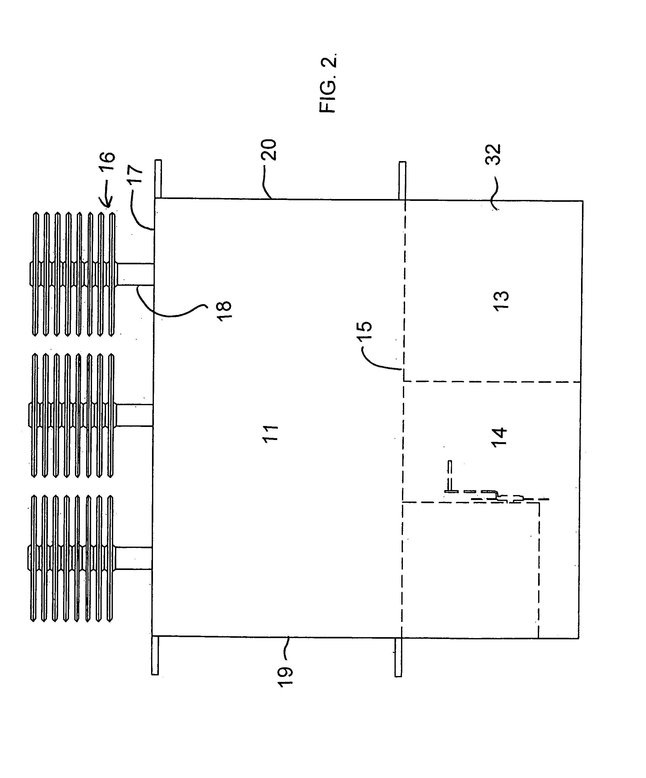
[0056]The apparatus comprises a housing 10 having a main transformer compartment 11, a first compartment 12, a second compartment 13 and a third compartment 14. The main transformer compartment 11 is mounted at the rear of the housing separated from the first, second and third compartments by a main vertical bulkhead 15. The main transformer compartment contains the transformer components which are of a construction well known to one skilled in the art. The transformer compartment 11 is filled with an insulating oil again of a conventional nature well known to one skilled in the art and includes an opening for filing and an opening for discharge of the oil as required. The transformer contains suitable windings and a tap switch which allows adjustment of the voltage. The oil is generally circulated using convection currents without the necessity for any moving pumps or the like. Cooling fins 16 are mounted on the rear of the housing outside of a rear wall 17 for communication of oil...


PUM


Abstract

A transformer is formed by a housing having a main transformer compartment, a first compartment for the input terminals for the main power supply, a second compartment for the output terminals to supply the load and a third compartment for a manually operable switching unit, where each of the compartments is maintained separately from each of the others and each has a manually openable interlocked cover which can be opened to provide access to an interior of the respective compartment. The switch assembly has switch contacts mounted within a switch container located within the third compartment and a manually operable member mounted one on side wall located within the third compartment outside the switch container for moving the switch contacts between open and closed positions. The switch container has a transparent window in a wall thereof through which the contacts can be observed and an insulating liquid bath maintained separate from an insulating liquid bath for the transformer assembly.

Description

BACKGROUND OF THE INVENTION[0001]Transformers serve an integral role in the delivery of electrical power from generation sources to specific point of use applications. Whether dry-type or liquid-filled, single-phase or three-phase, a wide variety of transformer types are often involved in the transformation of power throughout the electrical system, ultimately providing available power for consumption.[0002]There are many different applications for transformers. The type of transformer utilized for a specific requirement is often dictated by the service conditions and the amount of power required for a particular application. Focusing on liquid-filled transformers only, small residential loads quite often use single-phase transformers mounted overhead or a completely tamperproof version mounted at ground level. Larger commercial or industrial loads could use larger single-phase transformers or could deploy smaller three-phase transformers to reduce the voltage down to usable levels....

Claims


Application Information

Patent Timeline
Patent Type & Authority Patents(United States)
IPC IPC(8): E04H5/04H02B5/00
CPCH01F27/02H01F27/40H01F27/04H01H9/226H01H2009/0292
Inventor NORRIS, IAN H.BULLIS, MICHAEL L.KLAPONSKI, BRIAN F.MADRAY, WINSTON R.ENGEL, FLOYD E. A.
Owner CARTE INT
Why Eureka
Try Eureka