
Radiation image processing apparatus, image processing system, radiation image processing method, storage medium, and program

a radiation image and image processing technology, applied in the field of radiation image processing apparatus, image processing system, radiation image processing method, storage medium, and program, can solve the problems of image observer's problem of aliasing based on sampling theorem, normal unpredictable scattering rays,

Inactive Publication Date: 2006-11-28
CANON KK
View PDF15 Cites 32 Cited by
  • Summary
  • Abstract
  • Description
  • Claims
  • Application Information

AI Technical Summary

Benefits of technology

The present invention relates to an apparatus and method for processing a radiation image of an object obtained by radiography using a grid to remove scattered radiation. The apparatus includes a detection system for identifying image components caused by the grid, a generation system for generating the image components based on data from the radiation image and a predetermined speed of the grid, and an arithmetic system for removing the image components. The technical effects of the invention include improved image quality by removing image components caused by the grid, and improved efficiency in processing multiple radiation images by removing the image components.

Problems solved by technology

The generation process of scattered rays depends on the type of radiation, and the physical properties, structure, or the like of the object, and scattered rays are normally unpredictable.
However, in case of a digital radiation image, since an image signal must be sampled in a two-dimensional space, a problem of aliasing based on the sampling theorem is notable.
By contrast, in case of a digital radiation image obtained using a grid, a periodic stripe pattern formed by the grid has a very low frequency due to aliasing, or no aliasing is generated due to the sampling period but a low-frequency amplitude variation occurs, thus posing a problem with which the image observer must be concerned.
Upon capturing a digital radiation image by the digital conversion method of method 2, it is very difficult to remove an inappropriate grid stripe pattern due to, e.g., aliasing.
However, in such method, it is difficult to make high-density sampling in the two-dimensional space due to the arrangement of the electrical signal conversion elements of the sensor, resulting in a considerable increase in cost.
However, the aforementioned conventional radiation image processes and, especially, an image process that captures a radiation image by (method 2), i.e., using a sensor that makes direct sampling in a two-dimensional space and a grid, suffer the following problems.
In the arrangement proposed by Japanese Patent Laid-Open No. 9-75332 or the like, it is very difficult to completely match the spacing of grid stripes with the sampling pitch.
Hence, it is very difficult to completely match the spacing of grid stripes with the pixel pitch (sampling pitch) of the sensor due to these factors.
As a result, the use efficiency of the radiation dose drops very much, thus disturbing satisfactory radiography.
Upon moving the grid, a drive system or the like used to move the grid results in an increase in cost and a bulky system, and an arrangement for adjustment control or the like of the relationship between the drive timing and radiation exposure timing, the relationship of the drive speed, and the like must be provided.
Therefore, the arrangement that moves the grid cannot always be adopted although it is effective for removing grid stripes as it has the aforementioned limitations.
In this case, fundamental wave components alone may be received due to blur resulting from two-dimensional dependency of the conversion process (energy conversion process) of the sensor.
However, a problem with the aforementioned filtering is that it is nearly impossible to limit the spatial frequency band of the image components themselves.
However, it is not effective to decrease the spatial sampling pitch for only the purpose of removing grid stripes since it leads to very high cost of the sensor due to factors such as a semiconductor process and the like, and results in radiation capture efficiency drop.
However, with this arrangement, the spatial frequency components of the grid stripes and effective image components inevitably overlap each other to some extent.
By contrast, when an image signal has steep portions (edge portion), since an image signal is expressed using considerably high-frequency components equal to or lower than the Nyquist frequency, problems (artifacts) are posed in portions that vary steeply.

Method used


Image

  • Radiation image processing apparatus, image processing system, radiation image processing method, storage medium, and program
  • Radiation image processing apparatus, image processing system, radiation image processing method, storage medium, and program
  • Radiation image processing apparatus, image processing system, radiation image processing method, storage medium, and program

Examples


first embodiment

[First Embodiment]

[0229]The present invention is applied to, e.g., an X-ray image capture apparatus 100 shown in FIG. 6.

100>

[0230]The X-ray image capture apparatus 100 of this embodiment is used to capture an X-ray image for medical use (for image diagnosis or the like), and comprises an X-ray generator 101 for generating X-rays toward an object 102 (human body in this case), a grid 103 for removing scattered X-rays from the object 102, a flat X-ray sensor 104 for detecting the distribution of the X-ray dose that has been transmitted through the object 102, a controller 105 (CONT) of the X-ray generator 101, and an analog / digital (A / D) converter 106 for converting an electrical signal output from the X-ray sensor 104 into digital data, as shown in FIG. 6.

[0231]The apparatus 100 also comprises a memory 107 for temporarily storing digital data output from the A / D converter 106 as objective image data, a memory 108 for storing data captured while no X-rays are generated, an arithmetic ...

second embodiment

[Second Embodiment]

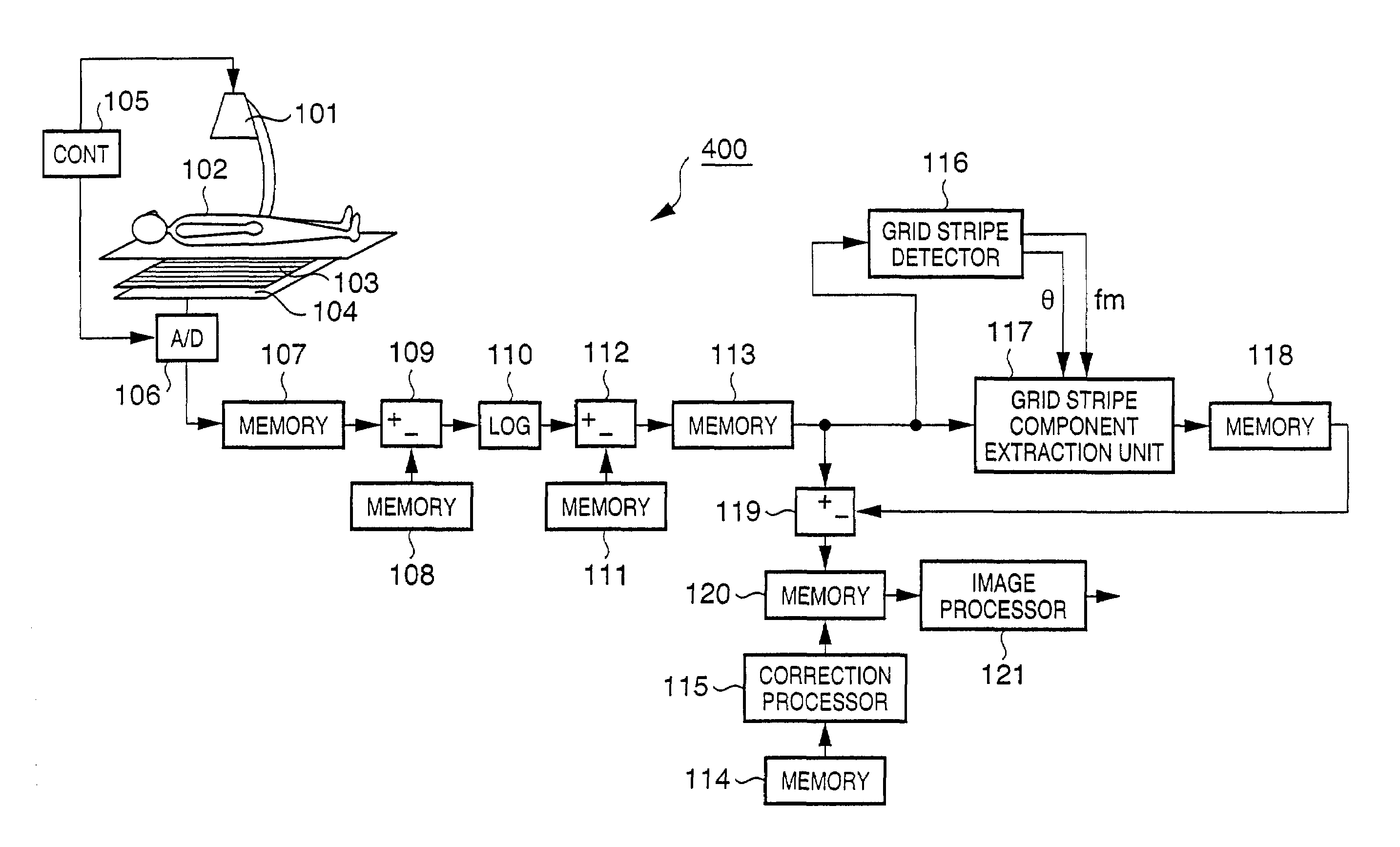
[0369]The present invention is applied to, e.g., an X-ray image capture apparatus 400 shown in FIG. 15.

[0370]Note that the same reference numerals in the X-ray image capture apparatus 400 in FIG. 15 denote the same parts as in the X-ray image capture apparatus 100 in FIG. 6, and a detailed description thereof will be omitted.

[0371]In the X-ray image capture apparatus 100 in FIG. 6, the correction processor 115 executes the defective pixel correction process using data in the memory 114 for the objective image data in the memory 113. By contrast, in the X-ray image capture apparatus 400 of this embodiment, as shown in FIG. 15, the correction processor 115 executes the defective pixel correction process using data in the memory 114 for the objective image data in the memory 120, i.e., for the objective image data after the grid stripe components have been removed.

[0372]Therefore, according to the X-ray image capture apparatus 400 of this embodiment, since the need f...

third embodiment

[Third Embodiment]

[0373]The present invention is applied to, e.g., an X-ray image capture apparatus 500 shown in FIG. 16.

[0374]Note that the same reference numerals in the X-ray image capture apparatus 500 in FIG. 16 denote the same parts as in the X-ray image capture apparatus 100 in FIG. 6, and a detailed description thereof will be omitted.

[0375]The X-ray image capture apparatus 500 of this embodiment has a detector (switch) 122 for detecting attachment of the grid 103 in addition to the arrangement of the X-ray image capture apparatus 100 in FIG. 6, as shown in FIG. 16.

[0376]The detector 122 supplies the detection result (grid attachment signal) of attachment of the grid 103 to the correction processor 115 and grid stripe detector 116.

[0377]When it is detected based on the grid attachment signal from the detector 122 that the grid 103 is attached, the correction processor 115 executes a defective pixel correction process that considers grid stripes, as has been explained in the ...


PUM


Abstract

The disclosure is made for an apparatus for processing a radiation image of an object obtained by radiography using a grid which is used to remove scattered radiation from the object.The apparatus includes generation means for generating image components due to the grid on the basis of data of the radiation image, to remove the image components due to the grid from the radiation image.

Description

FIELD OF THE INVENTION[0001]The present invention relates to an apparatus, a system, a method, a program, and a computer-readable storage medium storing the program, for a radiation image of an object obtained by radiography using a grid which is used to remove scattered radiation from the object.BACKGROUND OF THE INVENTION[0002]Conventionally, a technique for visualizing the interior of an object by irradiating an object (article) with radiation represented by X-rays and imaging the spatial distribution (radiation distribution) of radiation components which have been transmitted through the object is used. However, since the radiation generates scattered radiation (scattered rays) inside the object, the scattered radiation (scattered rays) is imaged together with directly transmitted radiation (direct rays) that has been transmitted through the object.[0003]The generation process of scattered rays depends on the type of radiation, and the physical properties, structure, or the like...

Claims


Application Information

Patent Timeline
Patent Type & Authority Patents(United States)
IPC IPC(8): G06K9/00G06T5/00H04N5/217H04N5/367
CPCG06T5/10H04N5/367G06T5/002G06T5/005G06T5/20G06T2207/10116H04N5/32G06T2207/30004A61B6/5252H04N25/68G06T5/77G06T5/70H04N23/30
Inventor INOUE, HITOSHINOKITA, MAKOTO
Owner CANON KK
Learn More