Fuel injection control device of internal combustion engine

a control device and internal combustion engine technology, applied in the direction of electrical control, machines/engines, automatic control of ignition, etc., can solve the problems of lowering the speed of the engine rotational speed ne, affecting the operation of the engine, so as to prevent the deterioration of exhaust gas, prevent excessive elevation of fuel pressure, and reduce the responsiveness of the fuel injection valve

Inactive Publication Date: 2006-12-05
MITSUBISHI ELECTRIC CORP
View PDF5 Cites 12 Cited by
  • Summary
  • Abstract
  • Description
  • Claims
  • Application Information

AI Technical Summary

Benefits of technology

[0039]The present invention has been made in view of the above-mentioned drawbacks of the conventional devices and it is an object of the present invention to provide a fuel injection control device of an internal combustion engine which can prevent the deterioration of an exhaust gas and the occurrence of an engine stop attributed to the lowering of the responsiveness of fuel injection valves by preventing the excessive elevation of a fuel pressure in the inside of a pressure storage chamber even when the minimum discharge flow rate of a high-pressure pump falls in a given rotational speed region which exceeds zero.
[0040]Further, it is another object of the present invention to provide a fuel injection control device of an internal combustion engine which can prevent the deterioration of an exhaust gas and the occurrence of an engine stop by preventing the excessive elevation of a fuel pressure in the inside of a pressure storage chamber while ensuring an air-fuel ratio which can maintain a stable combustion state in a given rotational speed region where the minimum discharge flow rate of a high-pressure pump exceeds zero.
[0042](2) Further, the present invention is, in the fuel injection control device of an internal combustion engine described in the above-mentioned (1), characterized in that the fuel increase correction means increases the basic fuel injection flow rate when the basic fuel injection flow rate becomes smaller than the minimum discharge flow rate of the high-pressure pump.
[0047]According to the fuel injection control device of an internal combustion engine of the present invention, it is possible to prevent the deterioration of the exhaust gas and the occurrence of the engine stop attributed to the lowering of the responsiveness of the fuel injection valve by preventing the excessive elevation of the fuel pressure in the inside of the pressure storage chamber even in the given rotational speed region where the minimum discharge flow rate of the high-pressure pump exceeds zero.
[0048]Further, according to the present invention, it is possible to attain the fuel injection control device of an internal combustion engine of the present invention which can prevent the deterioration of the exhaust gas and the occurrence of the engine stop by preventing the excessive elevation of the fuel pressure in the inside of the pressure storage chamber while ensuring the air-fuel ratio which can maintain the stable combustion state even in the given rotational speed region where the minimum discharge flow rate of the high-pressure pump exceeds zero.

Problems solved by technology

However, since this countermeasure requires the remodeling of the discharge flow rate control valve 10, the manufacturing cost is pushed up.
However, as a drawback of such a countermeasure, the valve-closing response property of the spill valve 12 at the time of performing the normal control is lowered and there exists a possibility that the fuel pressure controllability is worsened.
Further, even when the above-mentioned countermeasures are put into practice, it is considered that similar drawbacks will arise when impurities contained in the fuel are stacked on a periphery of the spill valve 12 so that a passage area is narrowed or the spring force of the spring 13 is lowered along with the lapse of time.
However, compared to the lowering speed of the intake air flow rate, the lowering speed of the engine rotational speed NE is slow due to the inertia of motion of the engine.
In this manner, in a state that the discharge flow rate of the high-pressure pump 20 becomes larger than the fuel injection flow rate and hence, the fuel pressure PR is elevated and does not agree with the target fuel pressure PO, the combustion state which is optimum for the engine cannot be obtained whereby the exhaust gas is deteriorated or the fuel pressure PR becomes excessively high whereby the fuel injection valves 51 cannot be driven with the given response property and, in a worst case, there exists the fear of the occurrence of the engine stop.
However, such a conventional device requires a control system for the electromagnetic pressure release valve and hence, the manufacturing cost is pushed up.

Method used


Image

  • Fuel injection control device of internal combustion engine
  • Fuel injection control device of internal combustion engine
  • Fuel injection control device of internal combustion engine

Examples


embodiment 1

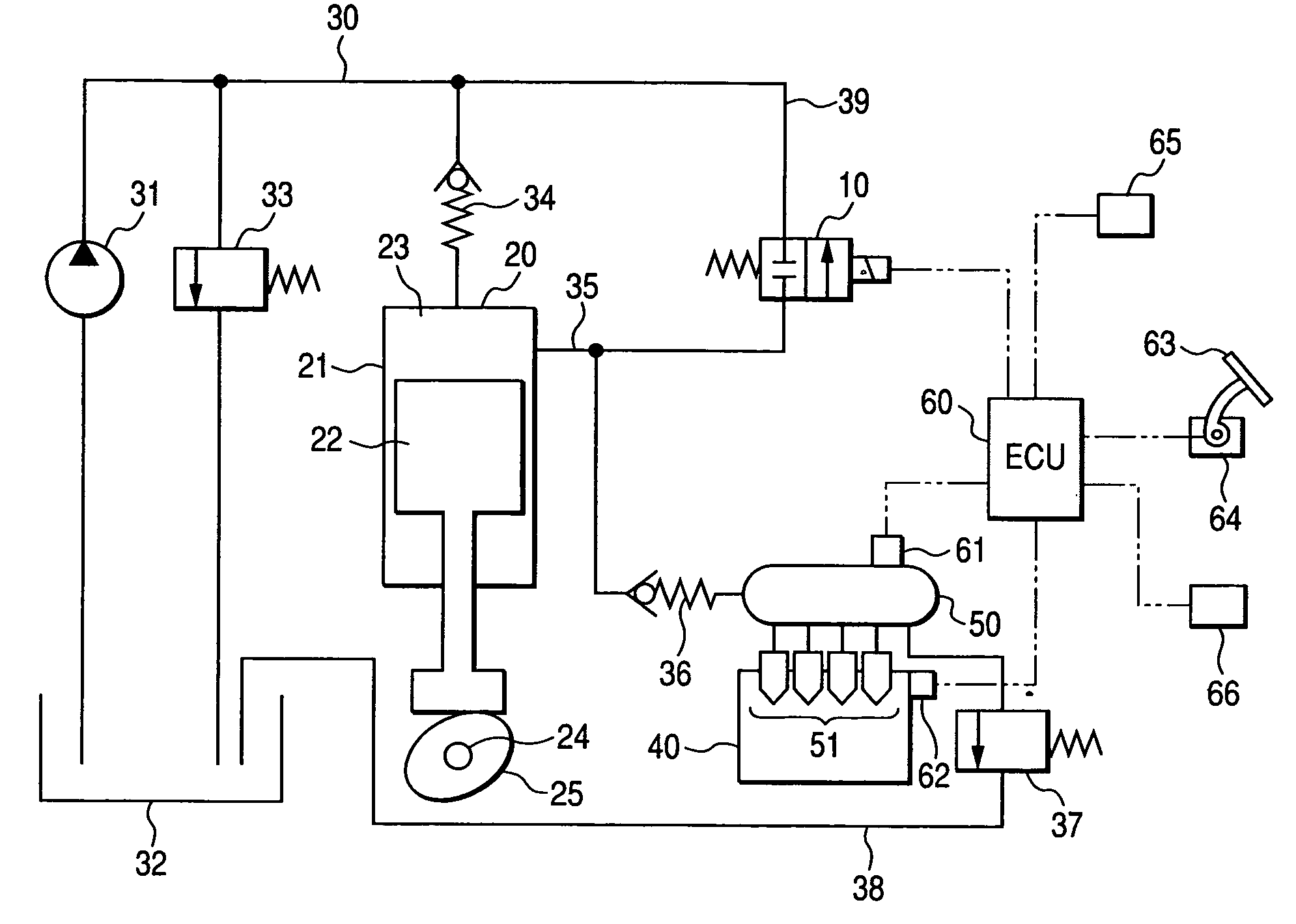
[0057]With respect to a fuel injection control device of an internal combustion engine to which the present invention is applicable, the previously-mentioned constitution of the fuel supply system in conjunction with FIG. 4 is basically directly applicable as it is and hence, the detailed explanation is omitted here.

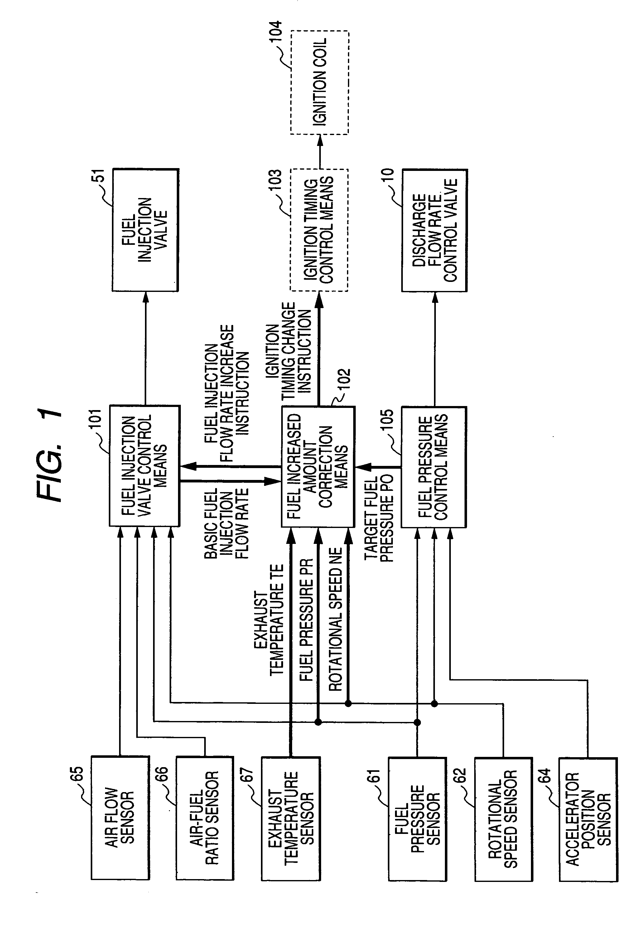
[0058]Hereinafter, the constitution of an ECU 60 which constitutes an electronic control unit of the fuel injection control device according to the embodiment 1 of the present invention is explained in conjunction with a block diagram shown in FIG. 1.

[0059]In FIG. 1, based on an engine operation state such as an intake air flow rate detected by an air flow sensor 65, an engine rotational speed NE detected by a rotational speed sensor 62 or a fuel pressure PR in the inside of a pressure storage chamber 50 detected by a fuel pressure sensor 61, fuel injection valve control means 101 calculates a basic fuel injection flow rate Qbase which makes an air-fuel ratio detected by...


PUM


Abstract

A fuel injection control device of an internal combustion engine includes fuel injection valve control means which calculates a basic fuel injection flow rate which becomes a target air-fuel ratio corresponding to an engine operation state and performs a driving control of the fuel injection valve, a fuel pressure sensor which detects a fuel pressure in the inside of the pressure storage chamber, a discharge amount control valve for controlling a fuel amount supplied to the pressure storage chamber from the high-pressure pump, and fuel pressure control means which controls the discharge amount control valve such that the fuel pressures in the inside of the pressure storage chamber agrees with a preset target fuel pressure, wherein the fuel injection control device includes fuel increase correction means which increases the basic fuel injection flow rate in a state that a rotational speed of the engine falls in a given preset rotational speed region where the minimum discharge flow rate of the high-pressure pump is expected to exceed zero and the fuel pressure in the inside of the pressure storage chamber is higher than the target fuel pressure.

Description

BACKGROUND OF THE INVENTION[0001]1. Field of the Invention[0002]The present invention relates to a fuel injection control device of an internal combustion engine, and more particularly to a fuel injection control device which directly injects fuel into the inside of a combustion chamber of an engine while controlling a fuel pressure in a pressure storage chamber to a high-pressure target fuel pressure.[0003]2. Description of the Related Art[0004]Recently, an internal combustion engine which controls a fuel pressure in a pressure storage chamber such that the fuel pressure assumes an optimum high pressure value for a combustion state and directly injects fuel into a combustion chamber has been commercialized and one example of the constitution of a fuel supply system of this type of internal combustion engine is explained in conjunction with FIG. 4.[0005]In FIG. 4, a high-pressure pump 20 is provided for pressurizing the fuel to a high pressure and the high-pressure pump 20 includes ...

Claims


Application Information

Patent Timeline
Patent Type & Authority Patents(United States)
IPC IPC(8): F01N3/00F01N3/20F01N3/24F02P5/15F02D41/04F02D41/38F02D41/40F02D45/00F02M55/02F02M59/20F02M59/36F02M63/02
CPCF02D41/3845F02M59/366F02M63/0225F02D41/1446F02D41/1454F02D41/187F02D2200/0602F02D2200/602F02D2250/21F02D2250/31
Inventor OONO, TAKAHIKO
Owner MITSUBISHI ELECTRIC CORP
Why Eureka
Try Eureka