Fuel injection control device of internal combustion engine

a technology of control device and internal combustion engine, which is applied in the direction of electric control, ignition automatic control, machines/engines, etc., can solve the problems of engine stopping, driven with desired response performance, etc., and achieve the effect of preventing the restarting of the injection of fuel

Inactive Publication Date: 2005-11-17
MITSUBISHI ELECTRIC CORP
View PDF6 Cites 18 Cited by
  • Summary
  • Abstract
  • Description
  • Claims
  • Application Information

AI Technical Summary

Benefits of technology

[0035] According to the fuel injection control device of an internal combustion engine according to the present invention, it is possible to prevent the restarting of the injection of the fuel while maintaining a state that the fuel pressure in the inside of the pressure storage chamber is excessively elevated during the fuel cut control whereby the deterioration of the exhaust gas and the generation of the engine stop can be obviated.
[0036] Further, according to the fuel injection control device of an internal combustion engine according to the present invention, at the time of performing the forced driving of the fuel injection valves by interrupting the fuel cut control, it is possible to suppress the generated torque of the engine to a minimum value and hence, it is possible to ensure the desired deceleration performance at the time of performing the forced driving of the fuel injection valves.
[0037] Still further, according to the fuel injection control device of an internal combustion engine according to the present invention, at the time of performing the forced driving of the fuel injection valves by interrupting the fuel cut control, the fuel injection amount is controlled such that the air-fuel ratio of the cylinders on which the forced driving is performed is set to a value close to theoretical air fuel ratio whereby the stable combustion state can be maintained even during the forced driving.

Problems solved by technology

Accordingly, the formation of the air-gas mixture optimum to the engine cannot be realized whereby an exhaust gas is deteriorated, or the fuel pressure PR becomes excessively high so that the fuel injection valve 51 cannot be driven with desired response performance, and the engine may be stopped in a worst case.

Method used


Image

  • Fuel injection control device of internal combustion engine
  • Fuel injection control device of internal combustion engine
  • Fuel injection control device of internal combustion engine

Examples


embodiment 1

[0046] With respect to a fuel injection control device of an internal combustion engine to which the present invention is applicable, the previously-mentioned constitution of the fuel supply system in conjunction with FIG. 8 is directly applicable as it is.

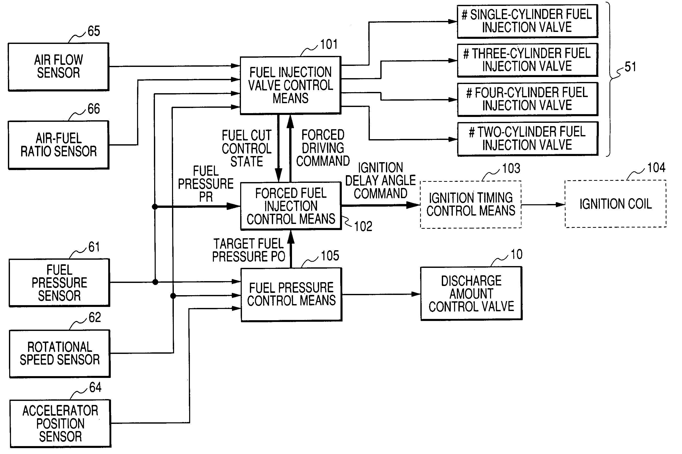
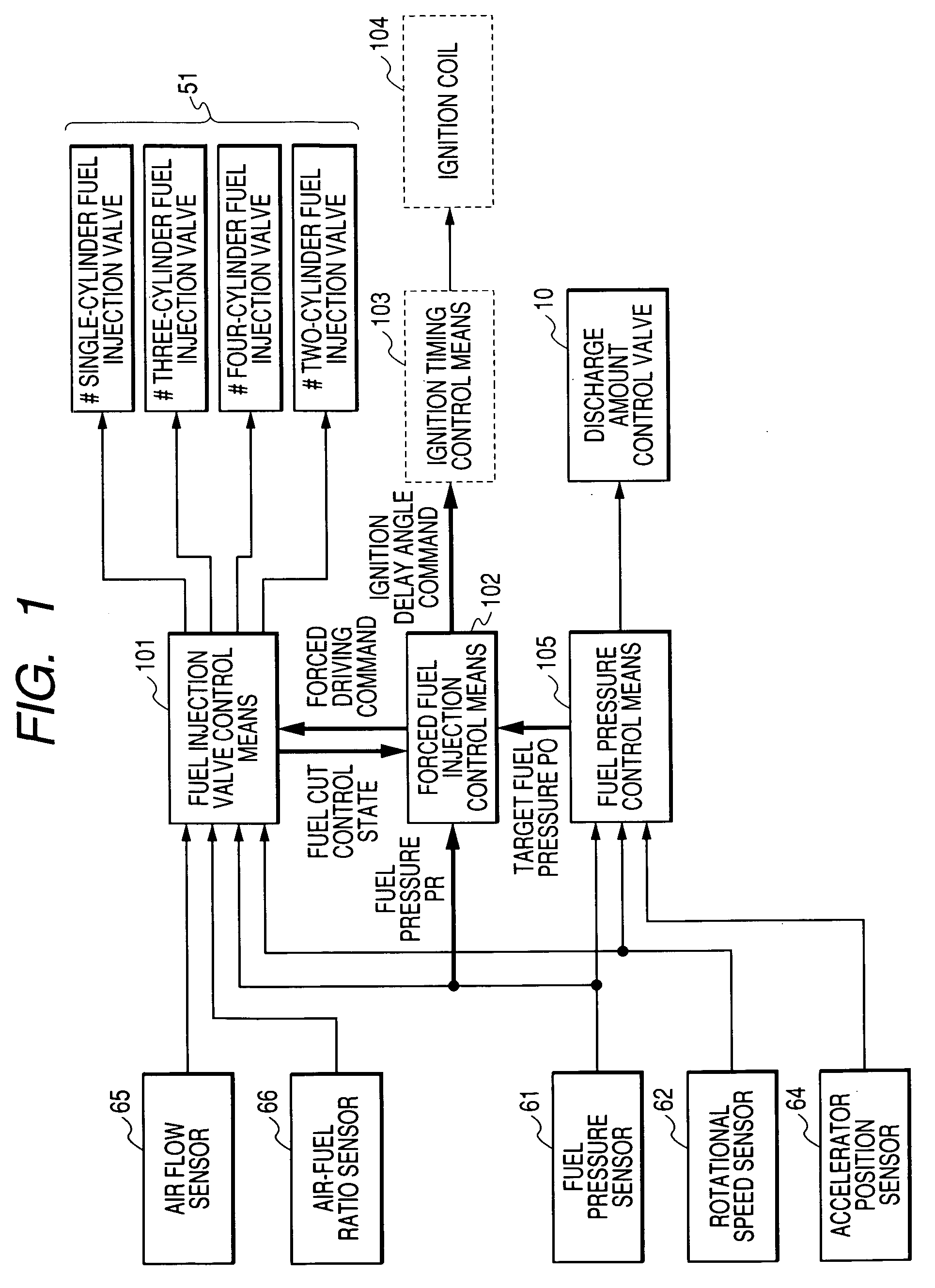
[0047] Hereinafter, the constitution of an ECU 60 which constitutes an electronic control unit of the fuel injection control device according to an embodiment 1 of the present invention is explained in conjunction with a block diagram shown in FIG. 1.

[0048] In FIG. 1, based on an engine operation state such as an intake air flow rate detected by an air flow sensor 65, an engine rotational speed detected by a rotational speed sensor 62 or a fuel pressure PR in the inside of a pressure storage chamber 50 detected by a fuel pressure sensor 61, fuel injection valve control means 101 calculates a fuel injection amount which makes an air-fuel ratio detected by an air-fuel ratio sensor 66 arranged in an exhaust pipe assume a target air...

embodiment 3

[0081]FIG. 5 is a flow chart showing the control operation of the forced fuel injection control means 102 according to the embodiment 3 of the present invention.

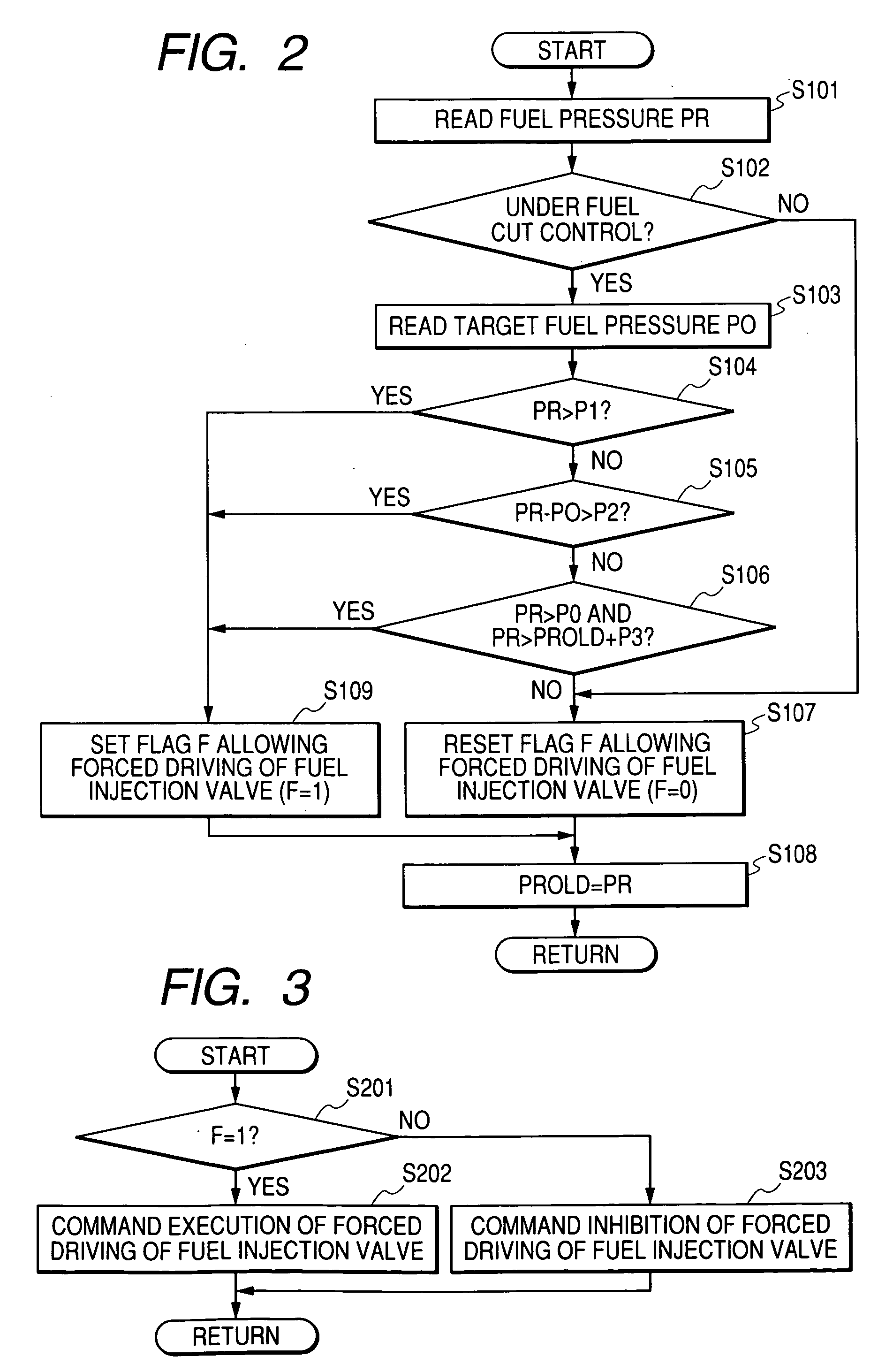
[0082] The control operation shown in FIG. 5 is executed based on the state of the forced driving permission flag F of the fuel injection valves 51 set in the above-mentioned flow chart shown in FIG. 2.

[0083] In FIG. 5, first of all, the forced fuel injection control means 102 determines whether the forced driving permission flag F is F=1 or not in step S401. When the determination is affirmative (F=1) in step S401, the processing advances to step S402 and the forced fuel injection control means 102 reads the intake air amount QA detected by the air flow sensor 65 and the processing advances to step S403. In step S403, the fuel injection amount QF which brings the theoretical air-fuel ratio with respect to the intake air amount QA read in step S402 is calculated and the processing in this step S403 is finished.

[0084] The ...


PUM


Abstract

The present invention provides a fuel injection control device which can prevent the occurrence of a phenomenon that when a pressure of fuel in the inside of a pressure storage chamber is elevated during a fuel cut, and the injection of fuel is restarted, the fuel is injected at a high fuel pressure largely different from a target fuel pressure. Accordingly, the fuel injection control device can prevent the deterioration of an exhaust gas and the occurrence of an engine stop. The fuel injection control device includes fuel injection valve control means which performs a driving control of the fuel injection valves, a fuel pressure sensor which detects a fuel pressure in the inside of the pressure storage chamber, a discharge amount control valve which controls a fuel amount supplied from the high-pressure pump to the pressure storage chamber, and fuel pressure control means which controls the discharge amount control valve such that the fuel pressure in the inside of the pressure storage chamber agrees with a target fuel pressure, wherein when the fuel pressure in the inside of the pressure storage chamber assumes a given pressure state during a fuel cut control, the forced fuel injection control means gives a driving instruction to the fuel injection valve control means to interrupt the fuel cut control thus enabling forced driving of the fuel injection valves of given cylinders.

Description

BACKGROUND OF THE INVENTION [0001] 1. Field of the Invention [0002] The present invention relates to a fuel injection control device of an internal combustion engine, and more particularly to a fuel injection control device which directly injects fuel into the inside of a combustion chamber of an engine while controlling a fuel pressure in a pressure storage chamber to a high-pressure target fuel pressure. [0003] 2. Description of the Related Art [0004] Recently, an internal combustion engine which controls a fuel pressure in a pressure storage chamber such that the fuel pressure assumes an optimum high pressure value for a combustion state and directly injects fuel into a combustion chamber has been commercialized and one example of the constitution of a fuel supply system of this type of internal combustion engine is explained in conjunction with FIG. 8. [0005] In FIG. 8, a high-pressure pump 20 is provided for pressurizing the fuel to a high pressure and the high-pressure pump 20...

Claims


Application Information

Patent Timeline
Patent Type & Authority Applications(United States)
IPC IPC(8): F02P5/15F02B17/00F02D17/02F02D41/02F02D41/12F02D41/38F02D43/00F02D45/00F02M37/04F02M55/02F02M59/20F02M59/36
CPCF02B17/005F02M37/04F02D41/3872F02D41/123
Inventor OONO, TAKAHIKODATE, TOSHIAKI
Owner MITSUBISHI ELECTRIC CORP
Why Eureka
Try Eureka