
Exhaust emission purifying apparatus for engine

a technology for purifying apparatus and exhaust, which is applied in mechanical apparatus, machines/engines, electric control, etc., can solve the problems of unfavorable global environment, excessive burden on the driver, and unnecessary consumption of fuel, so as to prevent the increase of the driver's burden, prevent the effect of unnecessary fuel consumption and protection of the global environmen

Active Publication Date: 2010-09-14
VOLVO LASTVAGNAR AB
View PDF18 Cites 9 Cited by
  • Summary
  • Abstract
  • Description
  • Claims
  • Application Information

AI Technical Summary

Benefits of technology

[0007]Therefore, in view of the problems encountered by the conventional technology as described above, the present invention has an object to provide an exhaust emission purifying apparatus in which, even if a use of the different kind of aqueous solution or the deficiency of a reducing agent is detected, restarting of an engine operation is permitted after stopping thereof until a vehicle mounting thereon the engine travels or runs for a predetermined distance after the detection, to thereby prevent an increase of a vehicle driver's burden, the unnecessary fuel consumption and the like.
[0011]By virtue of the exhaust emission purifying apparatus according to the present invention, it is judged that the liquid in the reducing agent container is the different kind of aqueous solution or that the reducing agent is deficient when the concentration of the reducing agent stored in the reducing agent container deviates from the predetermined range or when the residual amount of the reducing agent stored in reducing agent container becomes equal to or smaller than the predetermined amount. Then, when the restarting of the engine operation is made, the engine operation is inhibited from restarting when it is judged that the liquid in the reducing agent container is the different kind of aqueous solution or the reducing agent is deficient and also when the traveling distance of a vehicle after the judgment is judged to be equal to or longer than the predetermined distance, while the restarting of the engine operation is permitted for the rest conditions except for a condition of combination of the above-mentioned twice judgings. Therefore, even when it is detected that the liquid in the reducing agent container is the different kind of aqueous solution or the reducing agent is deficient, the inhibition of the restarting of the engine operation is suspended during a period of time until the vehicle travels for the predetermined distance after the above-mentioned detection. Accordingly, for example, even when the reducing agent becomes deficient immediately before reaching the destination of the vehicle, a driver of the vehicle is not forced to drive the vehicle to a point at which the reducing agent can be replenished after reaching the destination, and therefore, an increase of driver's burden can be prevented. Further, since the vehicle driving or the idling for the reducing agent replenishment is prevented, it is possible to achieve the prevention of the unnecessary fuel consumption and the protection of global environment.

Problems solved by technology

Nevertheless, if the restart of the engine operation is inhibited due to the reducing agent deficiency, for example when the reducing agent becomes deficient immediately before the engine-operated vehicle reaches its destination, it is required for the vehicle to unload cargo and to continue running by keeping the engine operation to a location where the reducing agent may be replenished.
In a case where the location at which the reducing agent can be replenished is not so near, an excessive burden is imposed on a vehicle driver and also a fuel is unnecessarily consumed due to the vehicle running irrelevant to the physical distribution.
Still further, such a situation is not preferable in view of the global environment.

Method used


Image

  • Exhaust emission purifying apparatus for engine
  • Exhaust emission purifying apparatus for engine
  • Exhaust emission purifying apparatus for engine

Examples


Embodiment Construction

[0018]Details of the present invention will be described hereunder, referring to the accompanying drawings.

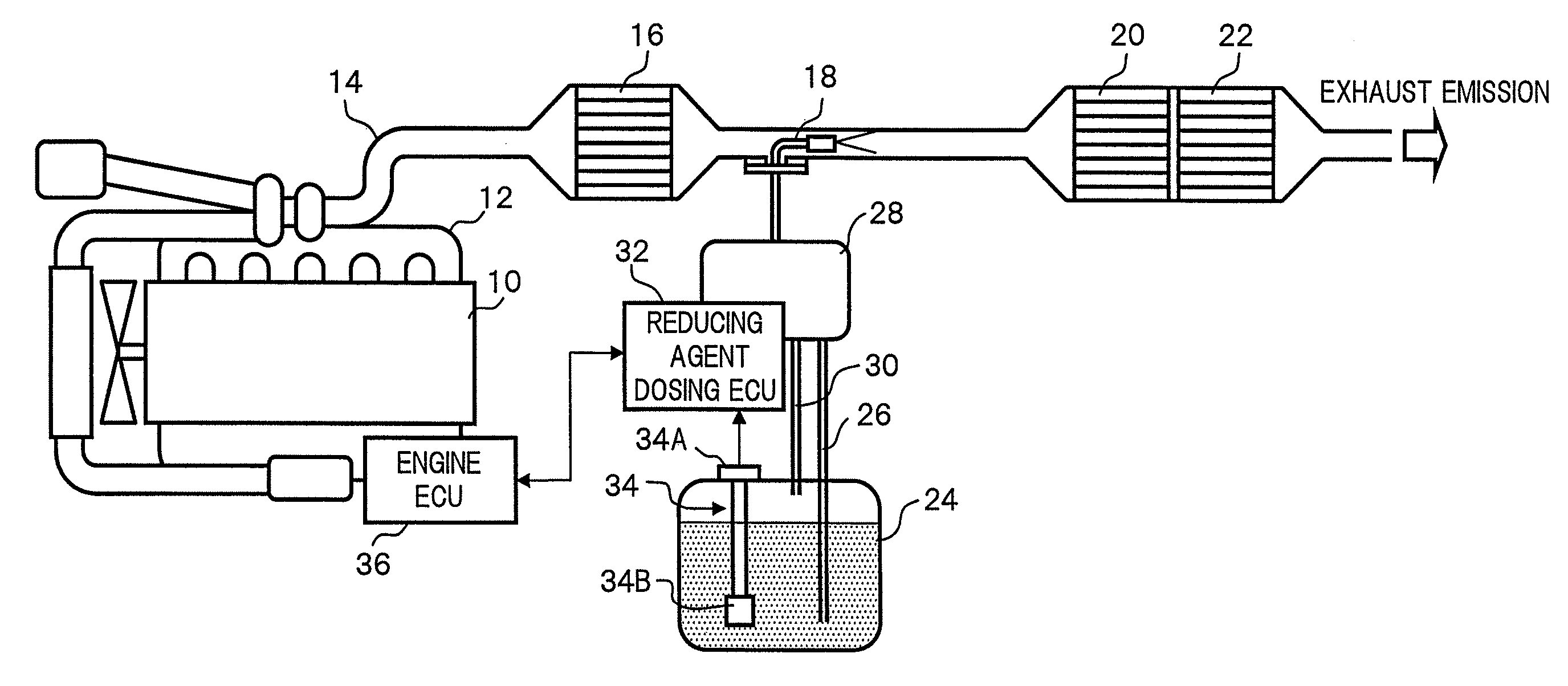
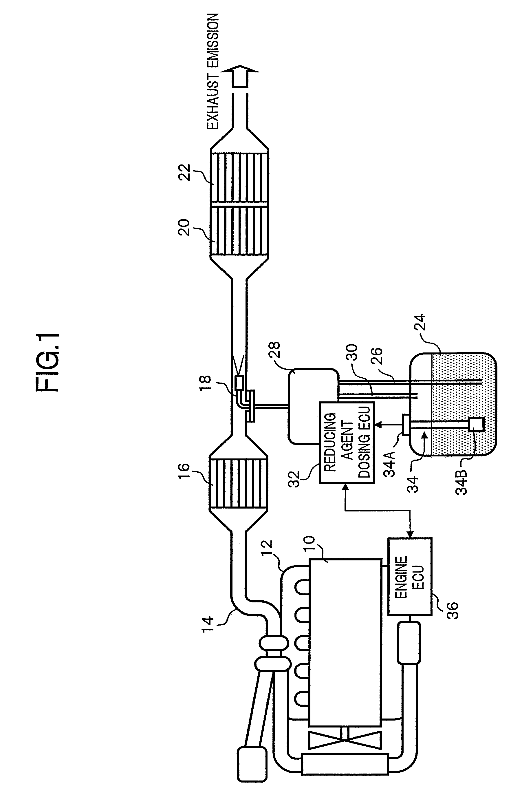
[0019]FIG. 1 shows an entire configuration of an exhaust emission purifying apparatus for using the urea aqueous solution which is precursor of ammonia, which is used as a reducing agent, to purify NOx contained in the engine emission by catalytic reduction reaction.

[0020]In an exhaust pipe 14 connected to an exhaust manifold 12 of an engine 10, there are disposed, along an exhaust emission flow direction in this order, a nitrogen oxidation catalytic converter 16 which oxidizes nitrogen monoxide (NO) into nitrogen dioxide (NO2), an injection nozzle 18 which injection-supplies the urea aqueous solution, a NOx reduction catalytic converter 20 which reductively purifies NOx with ammonia obtained by hydrolyzing the urea aqueous solution, and an ammonia oxidation catalytic converter 22 which oxidizes ammonia passed through the NOx reduction catalytic converter 20. Further, the urea ...


PUM


Abstract

When concentration of reducing agent stored in reducing agent container deviates from predetermined range or when residual amount of reducing agent becomes equal to or smaller than predetermined amount, it is judged that liquid in reducing agent container is different aqueous solution or reducing agent is deficient (abnormal judgment). Upon restarting of engine operation, if abnormal judgment is made and vehicle's travel for a predetermined distance or more occurs after abnormal judgment, restarting of engine operation is inhibited. At this time, if elapsed time until restarting of engine operation is performed from stopping moment of engine operation is less than predetermined time, engine operation is judged to be unintentionally stopped, and restarting of engine operation is permitted enabling a prompt action in emergency. But, even when abnormal judgment is made, if vehicle travels a distance less than predetermined distance after abnormal judgment, restarting of engine operation is permitted enabling vehicle to travel to reducing agent replenishing point.

Description

[0001]This application is a continuation of PCT / JP2006 / 310549, filed on May 26, 2006.BACKGROUND OF THE INVENTION[0002]1. Field of the Invention[0003]The present invention relates to an apparatus for purifying exhaust emission from an engine (to be referred to as an exhaust emission purifying apparatus), and in particular, to a technology for reductively purifying nitrogen oxides (NOx) in the exhaust emission using a reducing agent.[0004]2. Description of the Related Art[0005]As a catalytic purification system for removing NOx contained in the exhaust emission of an engine, there has been typically proposed, in Japanese Laid-open (Kokai) Patent Application Publication No. 2005-147118, an exhaust emission purifying apparatus in which a reducing agent or precursor thereof is dosed according to engine operating conditions to the exhaust emission streaming upstream of a reduction catalytic converter disposed in an engine exhaust pipe, so that NOx in the exhaust emission and the reducing ...

Claims


Application Information

Patent Timeline
Patent Type & Authority Patents(United States)
IPC IPC(8): F01N3/00
CPCF02D41/22F02D41/042F01N2610/02F01N2610/1406F02D2041/227F02D41/0275Y02T10/40
Inventor ESAKA, TAKEHIRO
Owner VOLVO LASTVAGNAR AB
Learn More