
Clothing dryer and blockage detection method thereof

a technology of blockage detection and dryer, which is applied in the field of dryer, can solve the problems of reducing the drying performance, increasing the noise reducing the power consumption of the draft fan, so as to achieve the effect of greatly enhancing the convenience of users

Active Publication Date: 2016-09-06
SAMSUNG ELECTRONICS CO LTD
View PDF9 Cites 2 Cited by
  • Summary
  • Abstract
  • Description
  • Claims
  • Application Information

AI Technical Summary

Benefits of technology

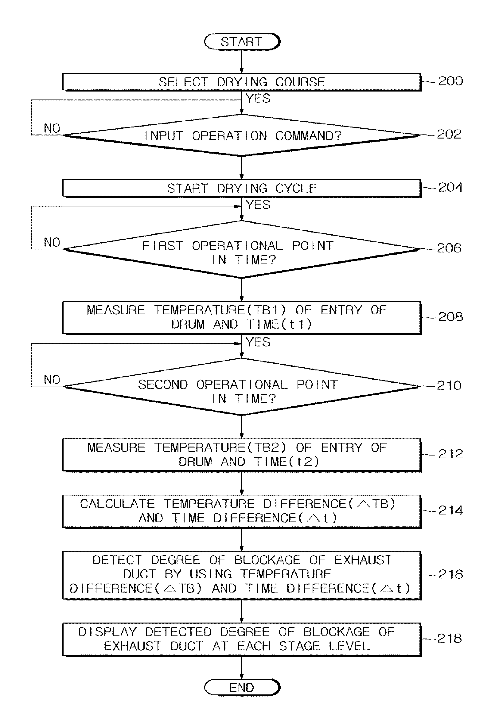
[0049]In accordance with the dryer and the blockage detection method suggested, by detecting and displaying the degree of a blockage of the exhaust duct that discharges air to the outside of the dryer during a drying process, a user may be able to easily confirm the degree of a blockage of the exhaust duct. In addition, by displaying the degree of a blockage of the exhaust duct at each stage level, a user is enabled to properly respond to the degree of a blockage of the exhaust duct, and by cleaning the exhaust duct at a proper time, the degradation of a drying performance may be prevented, and also the increase of the power consumption and noise may be prevented.
[0050]In addition, because the degree of a blockage of the exhaust duct is detected early in the drying process, a fire that may be caused by the overheating of the dryer may be prevented, and the distinction of the degree of a blockage of the exhaust duct may be possible with a high accuracy.
[0052]In addition, because the degree of a blockage of the exhaust duct may be directly acknowledged by a user during a blockage diagnosis process of the dryer, a user convenience may be greatly enhanced.

Problems solved by technology

However, the lint accumulates at the exhaust duct as the dryer is being used for a period of time, and as a result of the above, the flow of the air is not freely discharged to the outside of the dryer, and thus the drying performance is reduced, and the power consumption or the noise of a draft fan is increased.
However, because a conventional dryer is configured to detect the degree of blockage only during the drying process while containing the substance, when the substance is not present, the blockage detection function may not operate at all or may be provided with a large margin of error.
As a result, the suitability with respect to the installation environment may not be diagnosed at the time of an initial installation of the dryer, before the substance is introduced.

Method used


Image

  • Clothing dryer and blockage detection method thereof
  • Clothing dryer and blockage detection method thereof
  • Clothing dryer and blockage detection method thereof

Examples


Embodiment Construction

[0064]Reference will now be made in detail to the embodiments of the present disclosure, examples of which are illustrated in the accompanying drawings, wherein like reference numerals refer to like elements throughout.

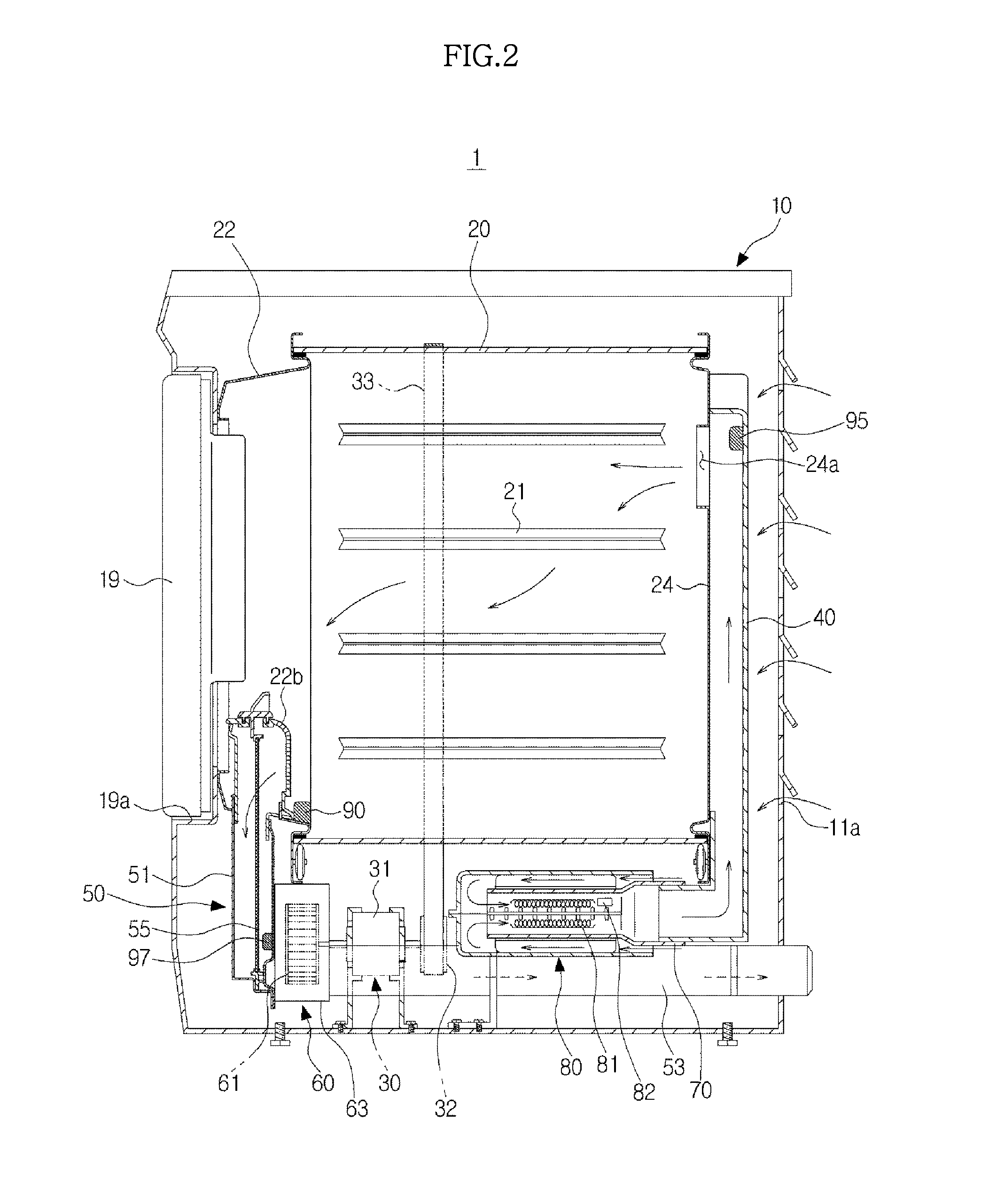
[0065]FIG. 1 is a perspective view of a dryer in accordance with an embodiment of the present disclosure, and FIG. 2 is a side cross-sectional view of the dryer illustrated on FIG. 1.

[0066]In FIG. 1 and FIG. 2, a dryer 1 in accordance with an embodiment of the present disclosure includes a body 10 composed approximately in a hexagonal shape, a drum 20 rotatably installed inside the body 10 and having a space in which a substance such as clothing, for example, is dried, a driving apparatus 30 to rotate the drum 20, and a hot air duct 70 to supply hot air to the drum 20.

[0067]The body 10 includes a cabinet 11, a top cover 12 to cover an upper portion of the cabinet 11, a front surface panel 13 disposed at a front surface of the cabinet 11, and a control panel 14 at whic...


PUM

PropertyMeasurementUnit
power capacityaaaaaaaaaa

Abstract

A method for detecting a degree of blockage of an exhaust duct includes detecting the temperature of air in an intake and exhaust system, calculating a rate of change of the detected temperature, and determining a degree of blockage of the exhaust duct based on the detected temperature and the rate of change of the detected temperature.

Description

CROSS-REFERENCE TO RELATED APPLICATIONS[0001]This application claims the priority benefit of Korean Patent Applications No. 10-2012-0033220, filed on Mar. 30, 2012 and No. 10-2012-0107504, filed on Sep. 26, 2012, in the Korean Intellectual Property Office, the disclosures of which are incorporated herein by reference.BACKGROUND[0002]1. Field[0003]The following description relates to a dryer configured to dry a substance such as clothing, and more particularly, to a dryer configured to detect and display the degree of an exhaust blockage of the dryer, and a blockage detection method thereof.[0004]2. Description of the Related Art[0005]A dryer is an apparatus configured to dry a substance by supplying high-temperature moving air heated by a hot blast heater into an inside of a drying container (a drum) while the drum having the clothing accommodated to be dried (hereinafter called a substance) is being rotated. The dryer as such may be classified into an exhaust-type dryer configured ...

Claims


Application Information

Patent Timeline
Patent Type & Authority Patents(United States)
IPC IPC(8): F26B25/00G01K13/02D06F58/28D06F58/20D06F58/22
CPCF26B25/009D06F58/28G01K13/02G01K2207/00D06F58/20D06F58/22D06F2058/2829D06F2058/2858G01K2013/024D06F37/42D06F34/20D06F58/50D06F2101/20D06F2103/08D06F2103/32D06F2103/38D06F2105/28D06F2105/58G01K13/024
Inventor LEE, HYUNG WOOPARK, HEE BEOMYOO, SANG OHKANG, GEUNCHANG, PIL SOO
Owner SAMSUNG ELECTRONICS CO LTD
Learn More