Display control method and system and display device

a display control and display technology, applied in the field of multi-media control, can solve the problems of shortening the development period of the product, bringing a certain limitation, and unable to guarantee the real-time (real-time) service module of the display control module, so as to achieve effective resolution of a data real-timeness issue, efficient operation, and guarantee the effect of display bandwidth

Active Publication Date: 2016-02-02
HONOR DEVICE CO LTD
View PDF6 Cites 0 Cited by
  • Summary
  • Abstract
  • Description
  • Claims
  • Application Information

AI Technical Summary

Benefits of technology

[0015]The objectives of the embodiments of the present invention are to provide a display control method and system, an apparatus, and a device, so that a system runs with low power consumption while a system cost, real-timeness, and system operating efficiency are guaranteed.
[0025]In the embodiments of the present invention, first, data collection is performed on a status value of a display buffer to obtain a specific status value of the display buffer, where the status value of the display buffer reflects a change to a current load; the status value of the display buffer is compared with a preset warning value of the display buffer; it may be determined whether a status value of the display buffer corresponding to the current load is normal according to a comparison result; and a value of a depth of outstanding bus commands is adjusted accordingly, so that a bus is still capable of sending a data reading command, so as to guarantee display bandwidth and effectively resolve a data real-timeness issue. In addition, the adjustment does not affect priorities of other commands on the bus and ensures that an entire system efficiently runs. In comparison with Method 1, the increase of a cost and power consumption caused by adding other components may be avoided. Furthermore, adjusting the value of the depth of outstanding bus commands achieves lower power consumption as compared with an existing method of raising a bus frequency.

Problems solved by technology

Using an SOC chip as the main control chip effectively reduces the volume of a product and shortens the development period of the product, but at the same time, brings a certain limitation.
This latency varies according to different system loads and bus frequency states, so that the real-timeness of such a real-time (real time) service module as the display control module cannot be guaranteed.
1. By using double DDRs and corresponding design, the area of the chip increases as the display buffer increases. This raises a design cost and at the same time increases system power consumption. For a multimedia play field, especially a mobile multimedia field such as a mobile phone, the power consumption issue is not acceptable.
2. Since the display architecture and bus architecture are adjusted and optimized accordingly, an underlying driver needs to be re-developed so that the underlying driver supports an open operating system. This brings a high product cost.
1. After a high priority is configured for the display control module in the AXI bus, the display control module occupies most high-priority bandwidth in the AXI bus. This lowers utilization efficiency of DDR bandwidth. To improve bandwidth utilization efficiency of the DDR bandwidth, a system needs to operate at a relatively high frequency. This inevitably raises the operating power consumption of the system.
2. While a high priority is configured for the display control module in the AXI bus, the real-timeness of other real-time service modules is surely affected during the running process of the display control module. This increases their latency, thereby affecting the overall efficiency of the system.

Method used


Image

  • Display control method and system and display device
  • Display control method and system and display device
  • Display control method and system and display device

Examples


embodiment 1

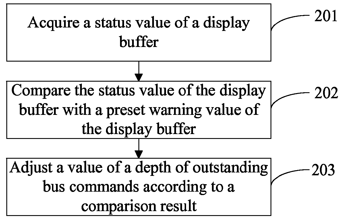
[0036]FIG. 2 shows a flowchart of a display control method according to Embodiment 1 of the present invention. The method is described in detail in the following:

[0037]In step S201, a status value of a display buffer is acquired.

[0038]Specifically, from a synchronous FIFO (First In First Out, first in first out) buffer, a synchronous write pointer signal Wr_ptr[n:0] and read pointer signal Rd_ptr[n:0] are read, and are sent to a comparing unit. In the comparing unit, a status value Fifo_full_level[n:0] of the display buffer is obtained according to addresses to which a read pointer and a write pointer point.

[0039]Specifically, obtaining a status of the buffer according to a read pointer and a write pointer is as follows: When each frame of image starts to be transmitted, display data is downloaded in advance to the display buffer in a blanking time; and after the valid time of display starts, the display data is output, the display data is output according to uniform bandwidth. When...

embodiment 2

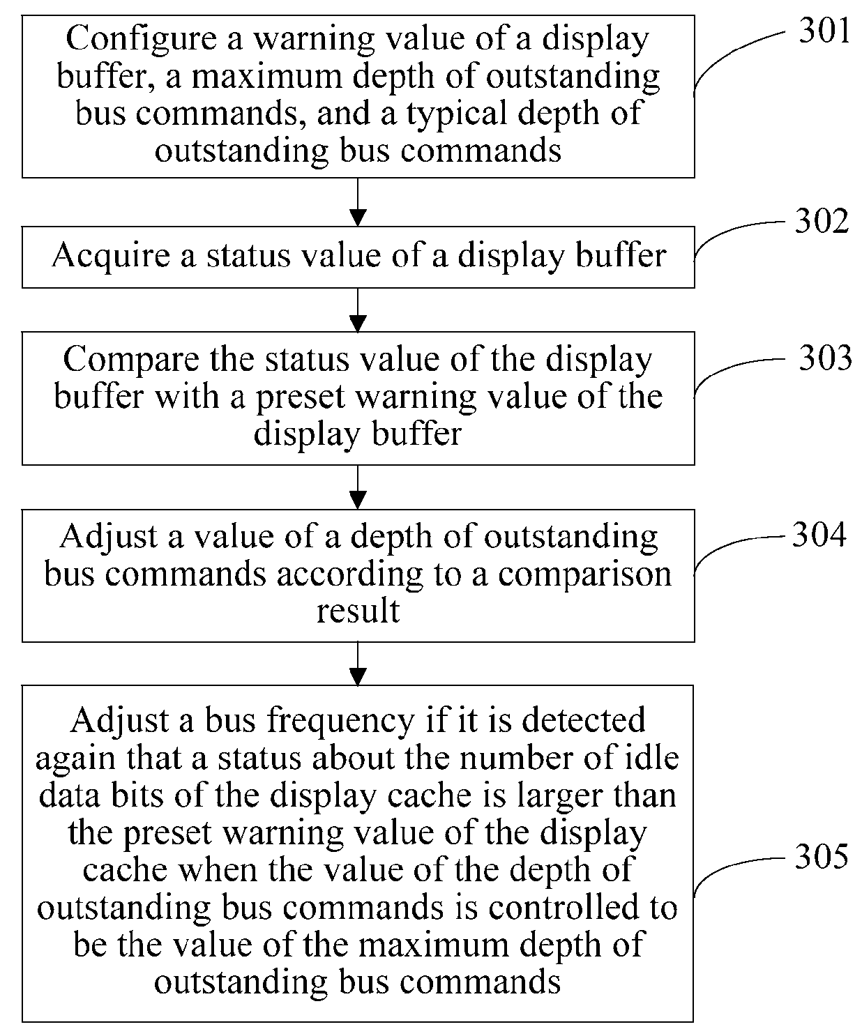
[0050]FIG. 3 shows a flowchart of a display control method according to Embodiment 2 of the present invention. The method is described in detail as follows:

[0051]In step S301, a warning value of a display buffer, a maximum depth of outstanding bus commands, and a typical depth of outstanding bus commands are configured.

[0052]In this embodiment, display bandwidth is guaranteed by adjusting the maximum depth of outstanding bus commands and the typical depth of outstanding bus commands according to a change to a status value of the display buffer, where the status value of the display buffer is reflected by the load of a system.

[0053]Setting the warning value of the display buffer, the maximum depth of outstanding bus commands, and the typical depth of outstanding bus commands is already introduced in Embodiment 1, and is not repeated herein.

[0054]In step S302, a status about the number of idle data bits of the display buffer is acquired.

[0055]In the method described in step S201 accor...

embodiment 3

[0063]FIG. 4 is a block diagram of a display control system according to Embodiment 3 of the present invention.

[0064]The display control system according to the embodiment of the present invention includes:

[0065]a configuring unit 401, configured to obtain a relatively good warning value of a display buffer, a maximum depth of outstanding bus commands, and a typical depth of outstanding bus commands according to system-level simulation of a typical scenario of a system, and perform fine adjustment through a test;

[0066]an acquiring unit 402, configured to acquire a status value of the display buffer; where:

[0067]the acquiring unit 402 includes:

[0068]a reading module 4021, configured to read a read pointer signal and a write pointer signal of the display buffer; and

[0069]a first comparing module 4022, configured to compare addresses to which a read pointer and a write pointer point and obtain the status value of the display buffer.

[0070]Specifically, from a synchronous FIFO (First In ...


PUM


Abstract

The present invention provides a display control method and system, and a display device. The method includes acquiring a status value of a display buffer; comparing the status value of the display buffer with a preset warning value of the display buffer; and adjusting a value of a depth of outstanding bus commands according to a comparison result. In the embodiments of the present invention, a status value of the display buffer is compared with a preset warning value of the display buffer, where the status value of the display buffer reflects a change to a current load; it may be determined whether a status value of the display buffer corresponding to the current load is normal according to a comparison result; and a value of a depth of outstanding bus commands is adjusted accordingly, effectively resolve a data real-timeness issue, and ensure that an entire system efficiently runs.

Description

CROSS-REFERENCE TO RELATED APPLICATIONS[0001]This application claims priority to Chinese Patent Application No. 201210165572.6, filed on May 25, 2012, which is hereby incorporated by reference in its entirety.FIELD OF THE INVENTION[0002]The present invention relates to the multimedia control field, and in particular, to a display control method and system and a display device.BACKGROUND OF THE INVENTION[0003]Currently, a display part of a multimedia device may be generally divided into two parts: a main control chip and a display module group. The main control chip includes a processor, a graphics engine module, a video codec module, and a display control module, and is configured to send obtained image data to the display module group by using a specific interface protocol according to a user requirement. The display module group includes a display screen and a display driving chip, and is mainly configured to receive, according to a particular interface protocol, image data sent b...

Claims


Application Information

Patent Timeline
Patent Type & Authority Patents(United States)
IPC IPC(8): G06T1/60G09G5/00G09G3/20
CPCG06T1/60G09G3/2096G09G5/006G09G2350/00G09G2360/12G09G2360/121
Inventor LI, ZHEHUANG, JUNLU, JIAYINHE, JIANBO
Owner HONOR DEVICE CO LTD
Why Eureka
Try Eureka