Method for operation of a burner and burner in particular for a gas turbine

Inactive Publication Date: 2006-12-05
SIEMENS AG
View PDF10 Cites 5 Cited by
  • Summary
  • Abstract
  • Description
  • Claims
  • Application Information

AI Technical Summary

Benefits of technology

[0006]Consequently, the object of the invention is to specify a method for the operation of a burner, and the burner itself, in particular in a gas turbine, which avoid the disadvantages of the known methods and in particular ensure a stable and continuous combustion process.
[0010]The method avoids the direction injection (“spraying”) of water into the center of the flame. As a consequence, the combustion process is particularly stable and continuous.
[0022]It is advantageous if the burner takes the form of a hybrid burner, for operation using gas and oil as alternative fuels, and the burner is connected to a gas premix line and an oil premix line.
[0027]It is advantageous if a valve, preferably a three-way valve, is used to feed the water into either the gas premix line or the oil premix line, depending at any instant on the operating mode of the burner in respect of the fuel which is being fed to it.

Problems solved by technology

A disadvantage of this method is that—in spite of its NOx-reducing effect—the direct injection of the water as mentioned, into the center of the flame, leads to an instability in the combustion process, particularly in respect of the stability of the flame produced by the burner, because the flame is partially extinguished, and / or inhibited by the water fed into it.
If such extinction effects occur at several burners, the combustion process is unable to proceed in a stable and continuous manner.

Method used


Image

  • Method for operation of a burner and burner in particular for a gas turbine
  • Method for operation of a burner and burner in particular for a gas turbine

Examples


Embodiment Construction

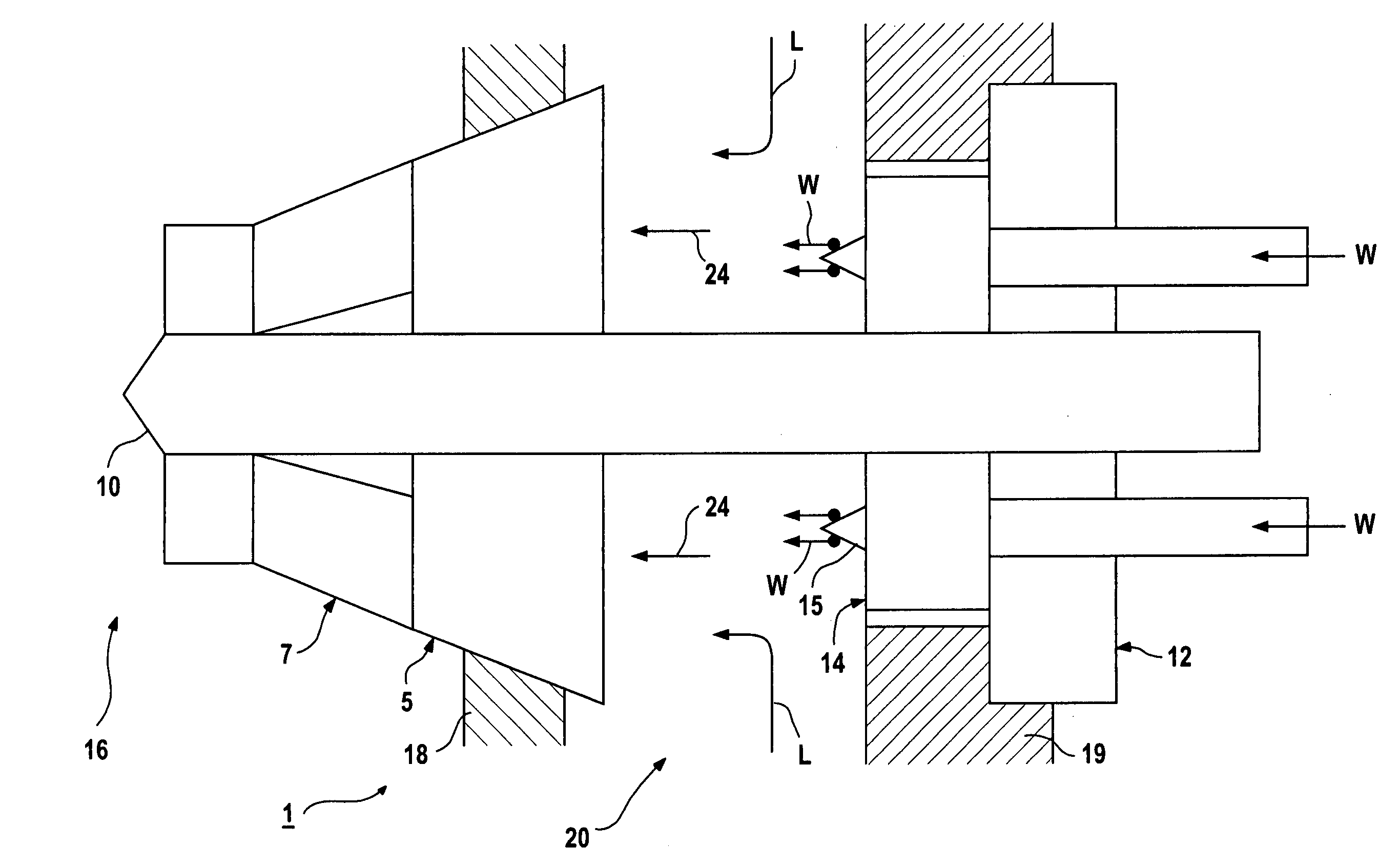
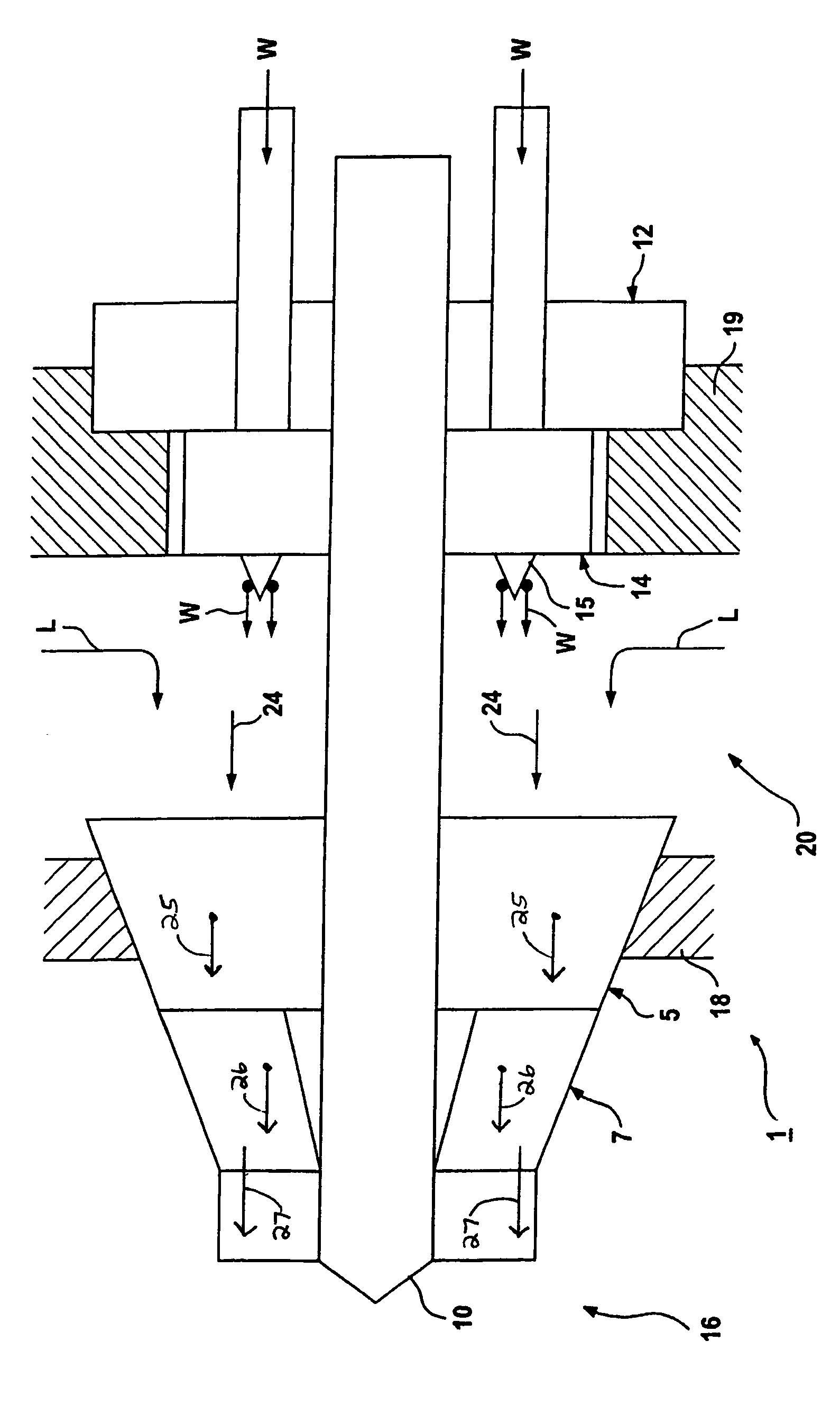
[0031]A burner 1 in accordance with the invention takes the form of a hybrid burner for operation with either oil or gas as alternative fuels. It comprises a gas premix burner 5, an oil premix burner 7, plus an oil and gas diffusion burner and pilot burner 10. It includes in addition a burner end-plate 12 and a water / water vapor premix injection device 14.

[0032]The tip of the burner's oil and gas diffusion burner and pilot burner projects into a combustion chamber 16. The burner end-plate anchors the burner, on the combustion chamber side in the region of the gas premix burner against a combustion wall 18, and on the gas turbine external wall side against an external wall of the gas turbine 19.

[0033]Between the combustion chamber wall 18 and the external wall of the gas turbine 19 there is an air duct 20, by means of which combustion air L is fed to the burner 1. Water W is fed to the water / water vapor premix injection device 14.

[0034]No further details are shown of how the fuel is ...


PUM


Abstract

The invention relates to a method for operation of a burner, whereby a mixture used for burning is supplied to the burner in a two-stage process. In a first step atomised water is mixed with combustion air and said mixture is mixed with a fuel in a second step and then supplied to the burner. Said burner comprises means for carrying out the above method.

Description

CROSS REFERENCE TO RELATED APPLICATIONS[0001]This application is the U.S. National Stage of International Application No. PCT / EP03 / 00109, filed Jan. 8, 2003 and claims the benefit thereof. The International Application claims the benefits of European application No. 02001456.9 filed Jan. 21, 2002, both of the applications are incorporated by reference herein in their entirety.FIELD OF INVENTION[0002]The invention relates to a method for operation of a burner. It relates further to a burner, in particular for a gas turbine.BACKGROUND OF INVENTION[0003]In the case of a turbine, in particular a gas turbine, which is driven by means of a fossil fuel, a number of burners are generally provided, these being located in a combustion chamber in the turbine. The function of the burners is essentially to effect reliable ignition of a fuel mixture which is fed to the combustion chamber, in order to produce the hot gas required to drive the rotor blades of the turbine. In doing this the combusti...

Claims


Application Information

Patent Timeline
IPC IPC(8): F02C3/30F23C99/00F23D17/00F23L7/00F23R3/28F23R3/30
CPCF02C3/30F23D17/002F23L7/002F23R3/286
Inventor KESSLER, ALFRED
Owner SIEMENS AG
Why Eureka
Try Eureka