Apparatus and method for installation of subsea well completion systems

a technology for completion systems and equipment, applied in the direction of drilling machines and methods, borehole/well accessories, underwater drilling, etc., can solve the problems of increasing the cost of installation

Inactive Publication Date: 2006-12-05
FMC TECH INC
View PDF15 Cites 27 Cited by
  • Summary
  • Abstract
  • Description
  • Claims
  • Application Information

AI Technical Summary

Benefits of technology

[0007]In accordance with the present invention, therefore, a method and apparatus for installing a conventional subsea completion system are provided which eliminate the need for an open water riser. In one embodiment of the invention, the method comprising the steps of: (a) landing a tubing hanger in a wellhead; (b) installing a plug in the tubing hanger bore; (c) providing a tree adapter which comprises a production bore and a valve for controlling flow through the production bore; (d) connecting the tree adapter to the christmas tree with the production bore in alignment with the christmas tree bore; (e) connecting the christmas tree to the wellhead with the christmas tree bore in alignment with the tubing hanger bore; (f) connecting a THRT to the tree adapter; and (g) removing the plug from the tubing hanger bore through the THRT, the production bore and the christmas tree bore.
[0009]The use of the tree adapter to install the christmas tree offers several advantages over prior art systems. The tree adapter provides an effective barrier between the well bore and the environment during the installation process, thus eliminating the need for a riser for this purpose. In addition, the tree adapter allows the christmas tree to be deployed using cable or a drill string, both of which are significantly less expensive than using an open water riser.

Problems solved by technology

However, such a riser is still required for retrieving the wireline plug from the tubing hanger.
Open water risers are typically run from drilling rigs or similar surface facilities which are relatively expensive to rent and operate.
Moreover, since open water risers are usually time consuming to deploy, any well installation step which requires the use of an open water riser will necessarily be costly.

Method used


Image

  • Apparatus and method for installation of subsea well completion systems
  • Apparatus and method for installation of subsea well completion systems
  • Apparatus and method for installation of subsea well completion systems

Examples


Embodiment Construction

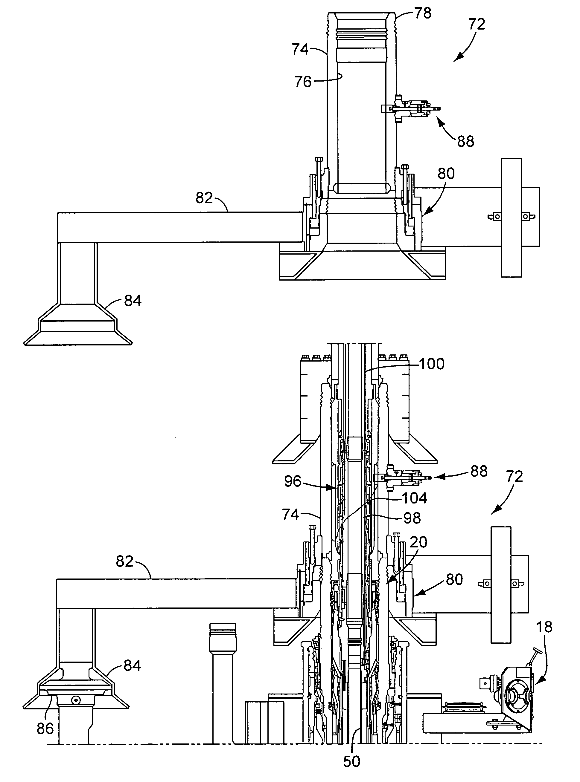
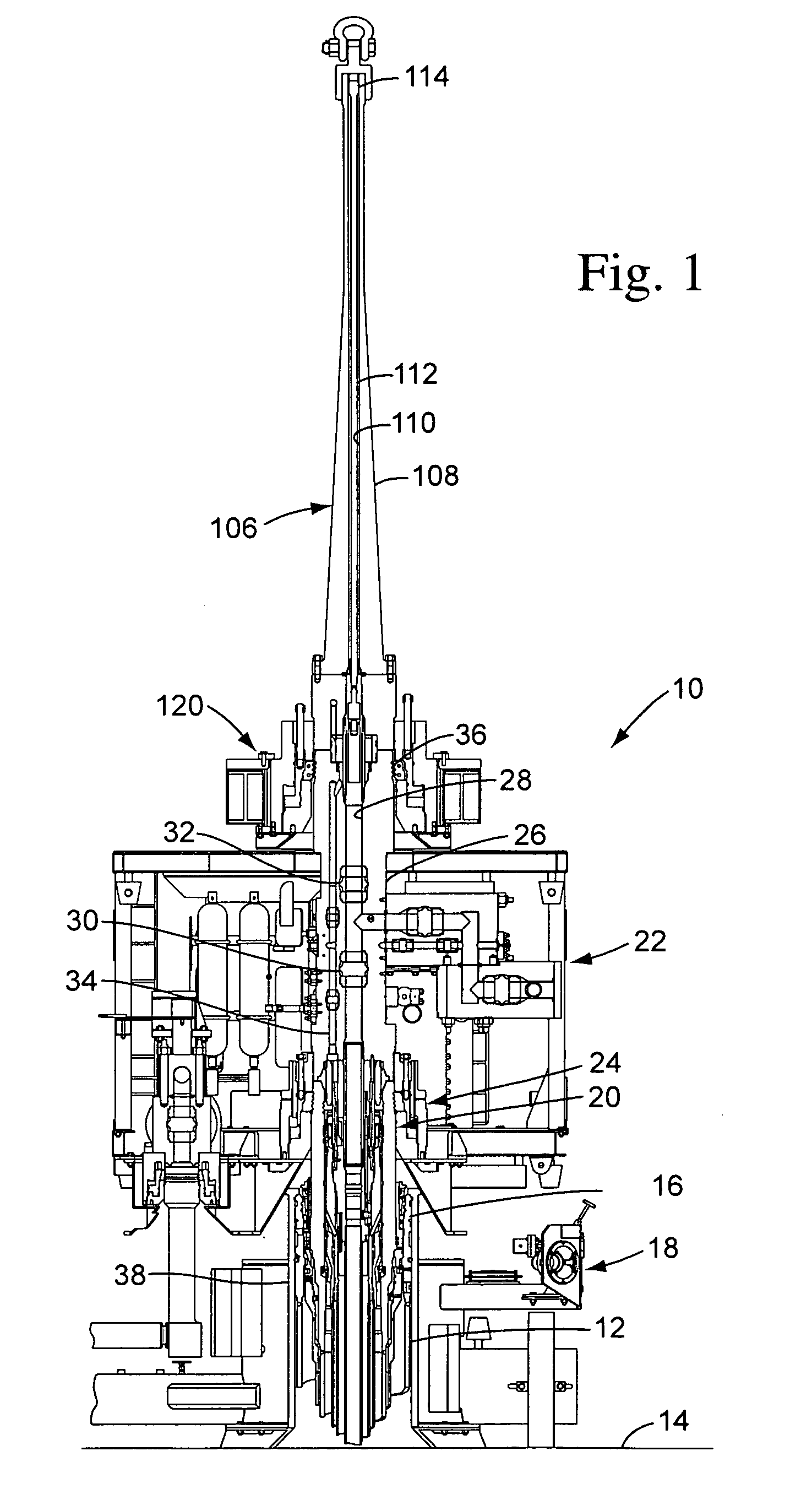
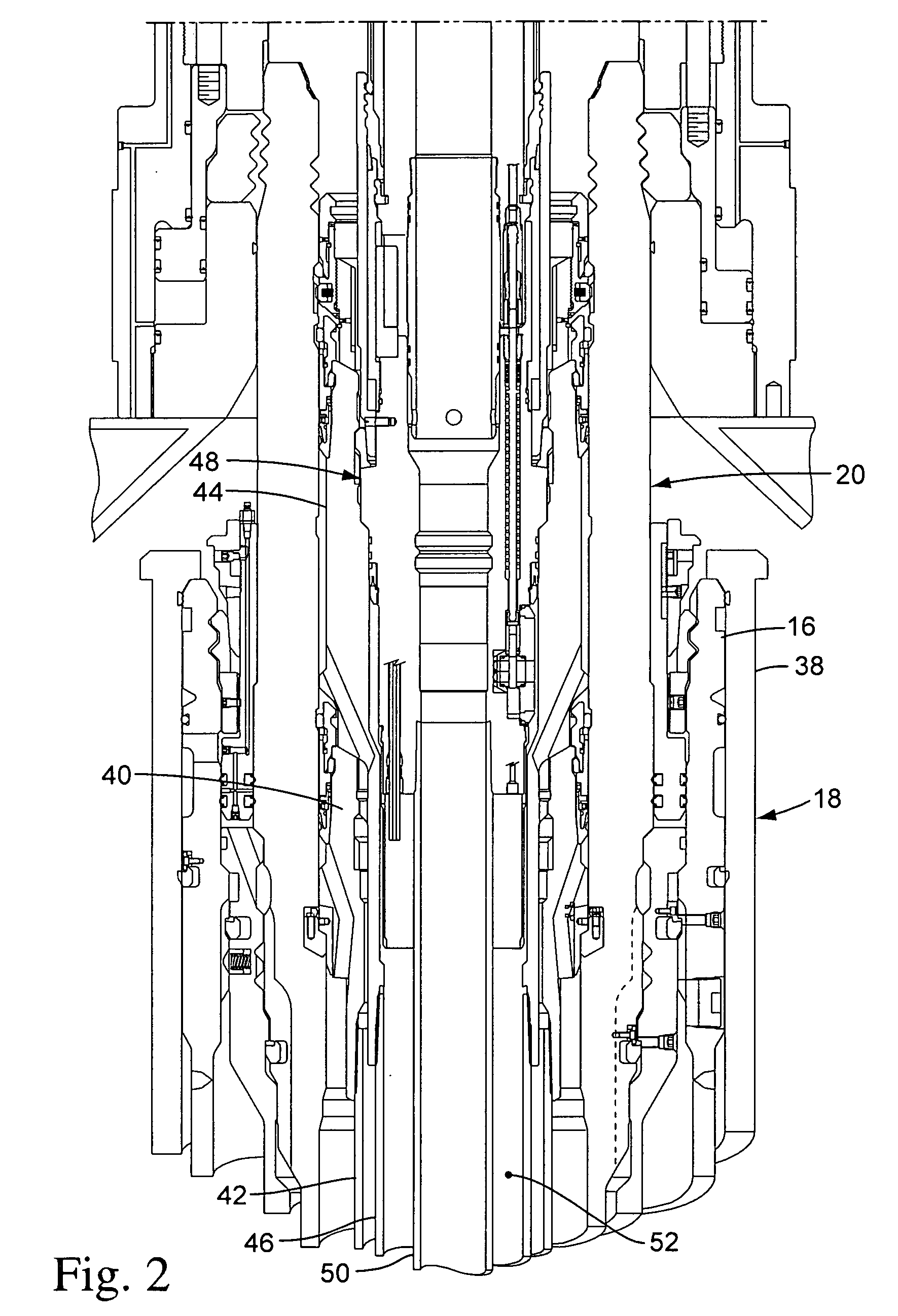
[0023]The apparatus and method of the present invention will be described herein in conjunction with the exemplary conventional completion system illustrated in FIG. 1, wherein certain components of the completion system are shown truncated for purposes of clarity. The conventional completion system, which is indicated generally by reference number 10, is shown to comprise a conductor pipe 12 which is installed in the sea floor 14 in the usual manner, a conductor housing 16 which is connected to the upper end of the conductor pipe, a CGB 18 which is secured to the conductor housing, a wellhead 20 which is landed in the conductor housing, and a conventional, or vertical, christmas tree 22 which is connected to the top of the wellhead using a suitable connector 24.

[0024]The illustrative christmas tree 22 comprises a tree body 26, a production bore 28 which extends generally axially through the tree body, and a number of valves, such as a production master valve 30 and a production swa...


PUM


Abstract

A method for installing a subsea completion system comprises installing a conductor housing on the sea floor, landing a wellhead in the conductor housing, securing a BOP to the wellhead, landing a casing hanger in the wellhead through the BOP, connecting a tubing hanger to a THRT, landing the tubing hanger in the wellhead or the casing hanger through the BOP, installing a wireline plug in the tubing hanger production bore through the THRT, retrieving the THRT, retrieving the BOP, securing an ROSL to the christmas tree, landing the christmas tree on the wellhead, and retrieving the wireline plug from the tubing hanger production bore using the ROSL.

Description

[0001]This application is a continuation of U.S. patent application Ser. No. 10 / 646,967 filed on Aug. 22, 2003, now U.S. Pat. No. 7,063,157, which is based on U.S. Provisional Patent Application No. 60 / 405,364 filed on Aug. 22, 2002.BACKGROUND OF THE INVENTION[0002]The present invention relates to completion systems for subsea oil and gas wells, and more specifically, to an apparatus and method for installing conventional completion systems.[0003]The installation of a conventional subsea completion system from a drilling rig typically includes the following steps: (1) install a conductor housing at the sea floor; (2) install a wellhead in the conductor housing; (3) land a blow-out preventer (“BOP”) stack on the wellhead; (4) land various casing hangers and their associated casing strings in the wellhead through the BOP; (5) land a tubing hanger and its associated production tubing string in the wellhead through the BOP using a tubing hanger running tool (“THRT”) suspended from a lan...

Claims


Application Information

Patent Timeline
Patent Type & Authority Patents(United States)
IPC IPC(8): E21B33/035E21B23/00E21B33/043E21B33/076E21B34/04
CPCE21B23/00E21B33/035E21B33/043E21B33/076E21B34/04E21B33/04
Inventor BARTLETT, CHRISTOPHER D.
Owner FMC TECH INC
Why Eureka
Try Eureka