Well packing

a well and packing technology, applied in the field of well packing, can solve the problems of not producing desired well fluid, unsatisfactory well fluid, and considerable problems to achieve a complete seal

Inactive Publication Date: 2006-12-05
HALLIBURTON ENERGY SERVICES INC
View PDF16 Cites 206 Cited by
  • Summary
  • Abstract
  • Description
  • Claims
  • Application Information

AI Technical Summary

Benefits of technology

[0009]The purpose of the present invention is to enable completion of reservoir sections by complete annular seal, at the same time as the invention allows variations in operational parameters and geological conditions without changing the functionality of the invention. The packer will expand less while the packer is inserted into the well in a drilling fluid or completing fluid than by exposure to hydrocarbons produced from the formation.

Problems solved by technology

An oil well normally penetrates formations with varying production features, which, in spite of the fact that the sand control screens are closed on the inside, may cause that undesired well fluid by-passes on the outside of these and flow into the section.
Therefore, it may be desired to control or shut off sections, which do not produce desired well fluid.
Further it is sensitive to changes in temperature and pressure, and there are often considerable problems to achieve a complete seal.
Another disadvantage is that the installation of the packer is expensive since well operations requiring complicated equipment are requisited.
This is impractical in an oil well, since the packer will expand before it is placed in the final operating position in the well.
Only minor impurities of remaining oil in the system will therefore result in an undesired early expansion.
This may lead to the polymer being produced with the produced fluids.

Method used


Image

  • Well packing
  • Well packing
  • Well packing

Examples


Embodiment Construction

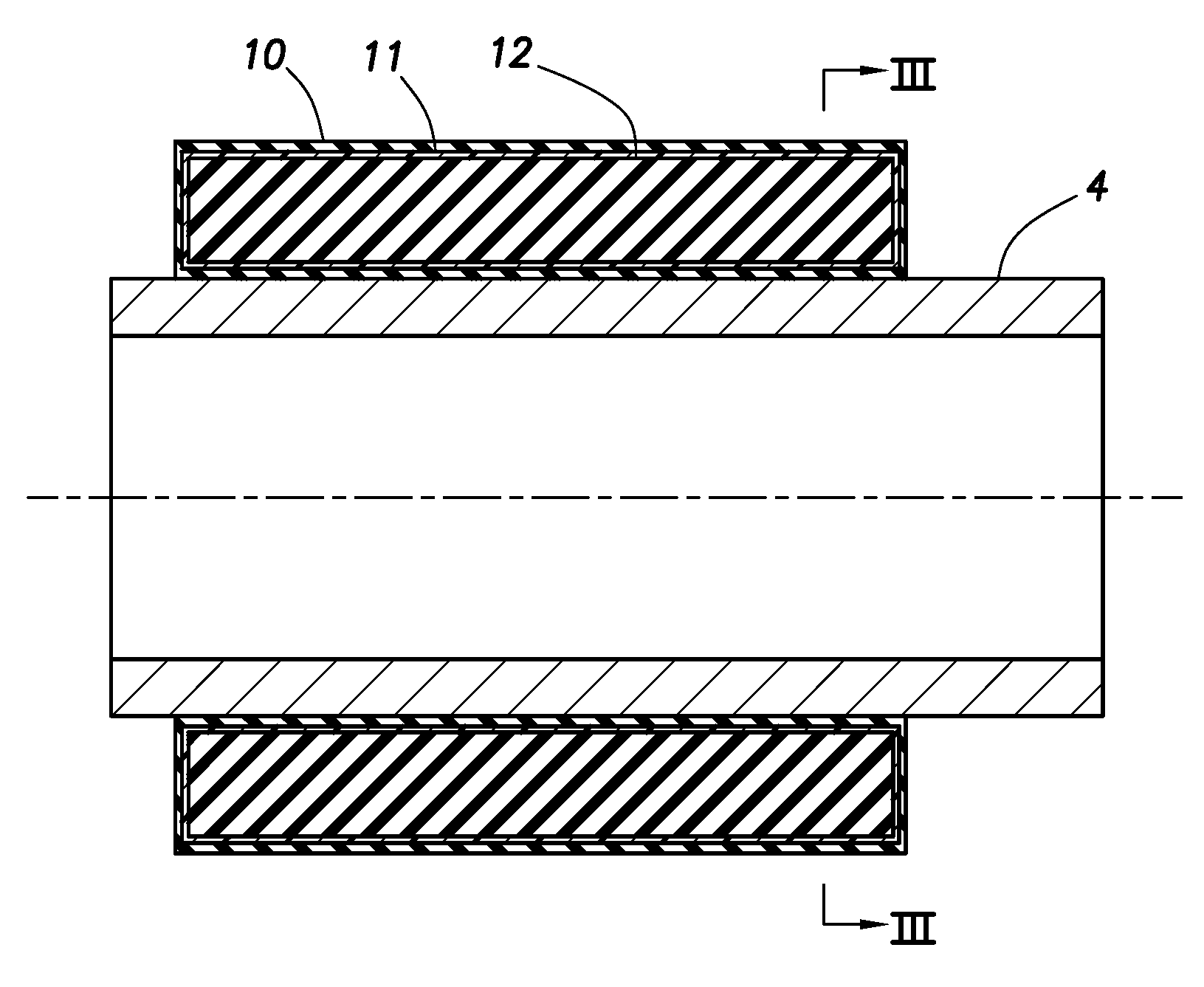
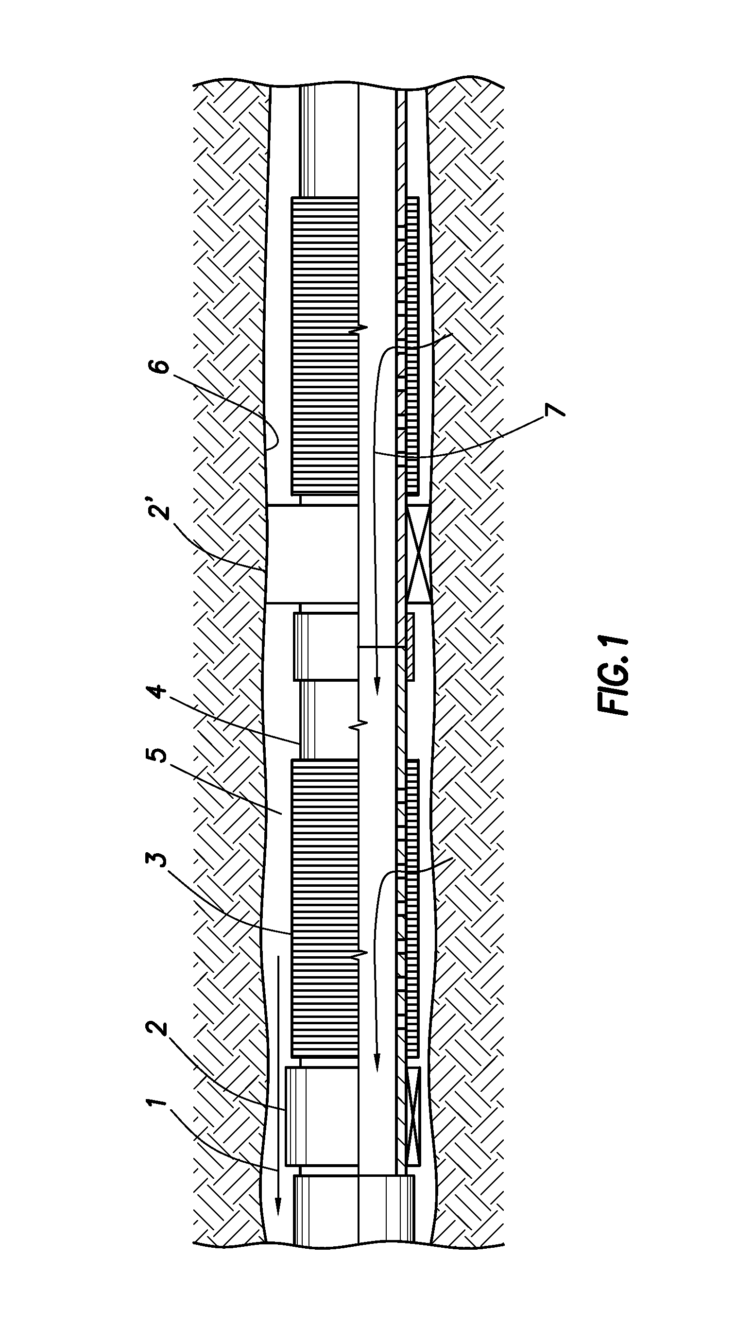
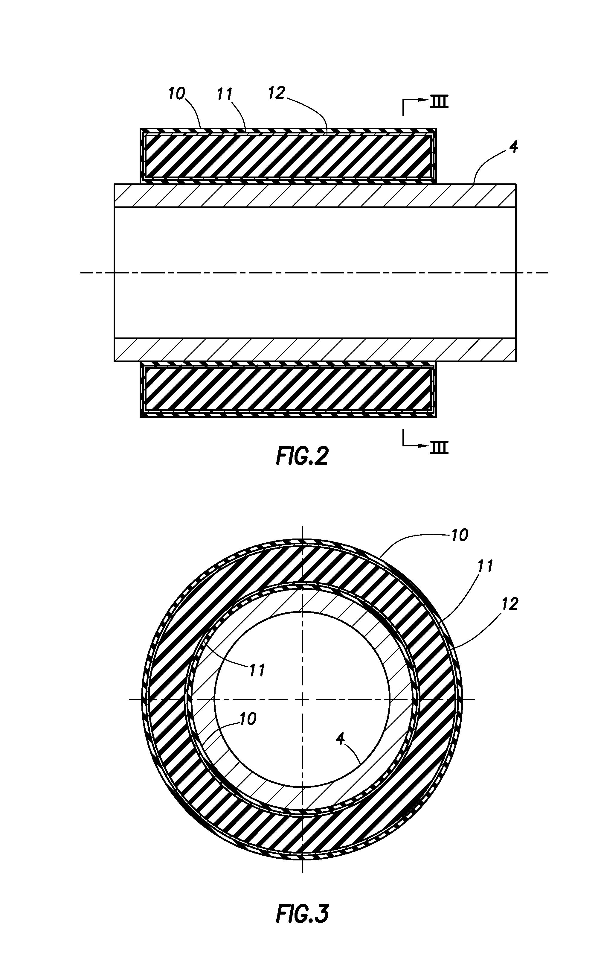
[0016]In the following, the invention is further described. The permanent annular packer 2 for use in hydrocarbon production wells, preferably oil production wells, is placed on the outside of a pipe 4, said packer expands by the core 12 swelling upon exposure for and absorption of hydrocarbons. The packer therefore seals the annular space 5 towards the well wall 6. The production well may be an open-hole well or a well with a casing, which is characterised in that the production tubing 4 is drawn in an open hole or that the production tubing 4 is drawn in a casing (not shown), respectively. Thus the annular space 5 consists of the external surface of the production tubing 4 and the bore hole wall, or the external surface of the production tubing 4 and the internal surface in the casing, respectively.

[0017]An oil stream 1 flows past a packer element 2 before the packer element 2 is expanded and sealing towards the well wall 6. A sand control filter 3 is attached to a production tubi...


PUM


Abstract

Annular packer (2) arranged on the outside of a production tubing (4) said packer comprises a core (12) comprising elastic polymer swelling by absorption of hydrocarbons. The core (12) may be surrounded by an external mantle of rubber (10), which is permeable to hydrocarbons and may be equipped with a reinforcement (11). The core (12) swells by absorption of hydrocarbons and the packer (2) expands thus in order to seal the annular space (5) between the production tubing (4) and the well wall (6).

Description

CROSS REFERENCE TO RELATED APPLICATION[0001]The present application is the U.S. national stage application of International Application PCT / NO01 / 00275, filed Jun. 29, 2001, which international application was published on Mar. 14, 2002 as International Publication WO 02 / 20941. The International Application claims priority of Norwegian Patent Application 20004509, filed Sep. 8, 2000.FIELD OF THE INVENTION[0002]The present invention relates to a method of the nature as stated in the introduction of claim 1 for sealing of an annular space between a well wall in a production well for hydrocarbons and a production tubing, to a peripheral annular packer of the nature as stated in the claims 2–10, comprising an expandable element mainly consisting of rubber material, and to the expanding annular packer for application in said methodBACKGROUND OF THE INVENTION[0003]Completion of oil wells with sand control screens in open hole is a simple and reliable method by to complete a reservoir secti...

Claims


Application Information

Patent Timeline
Patent Type & Authority Patents(United States)
IPC IPC(8): E21B33/12
CPCE21B33/12E21B33/1208E21B43/103
Inventor FREYER, JAN
Owner HALLIBURTON ENERGY SERVICES INC
Why Eureka
Try Eureka