Passive jet spoiler for yaw control of an aircraft

Inactive Publication Date: 2006-12-05
LOCKHEED MARTIN CORP
View PDF15 Cites 48 Cited by
  • Summary
  • Abstract
  • Description
  • Claims
  • Application Information

AI Technical Summary

Benefits of technology

[0009]A wing for an aircraft has a passive jet spoiler for providing yaw control by increasing drag on the wing. The spoiler comprises an inlet located near the leading edge of a lower surface of the wing and at least one outlet formed on the lower surface and/or on an upper surface of the wing. An internal passage connects the inlet and each outlet for allowing air to pass from the inlet to the outlets. Air passing across the lower surface enters the inlet and passes to the outlets. The air exits the outlets generally normal to the respective sur

Problems solved by technology

The separated flow increases the drag on the w

Method used


Image

  • Passive jet spoiler for yaw control of an aircraft
  • Passive jet spoiler for yaw control of an aircraft
  • Passive jet spoiler for yaw control of an aircraft

Examples


second embodiment

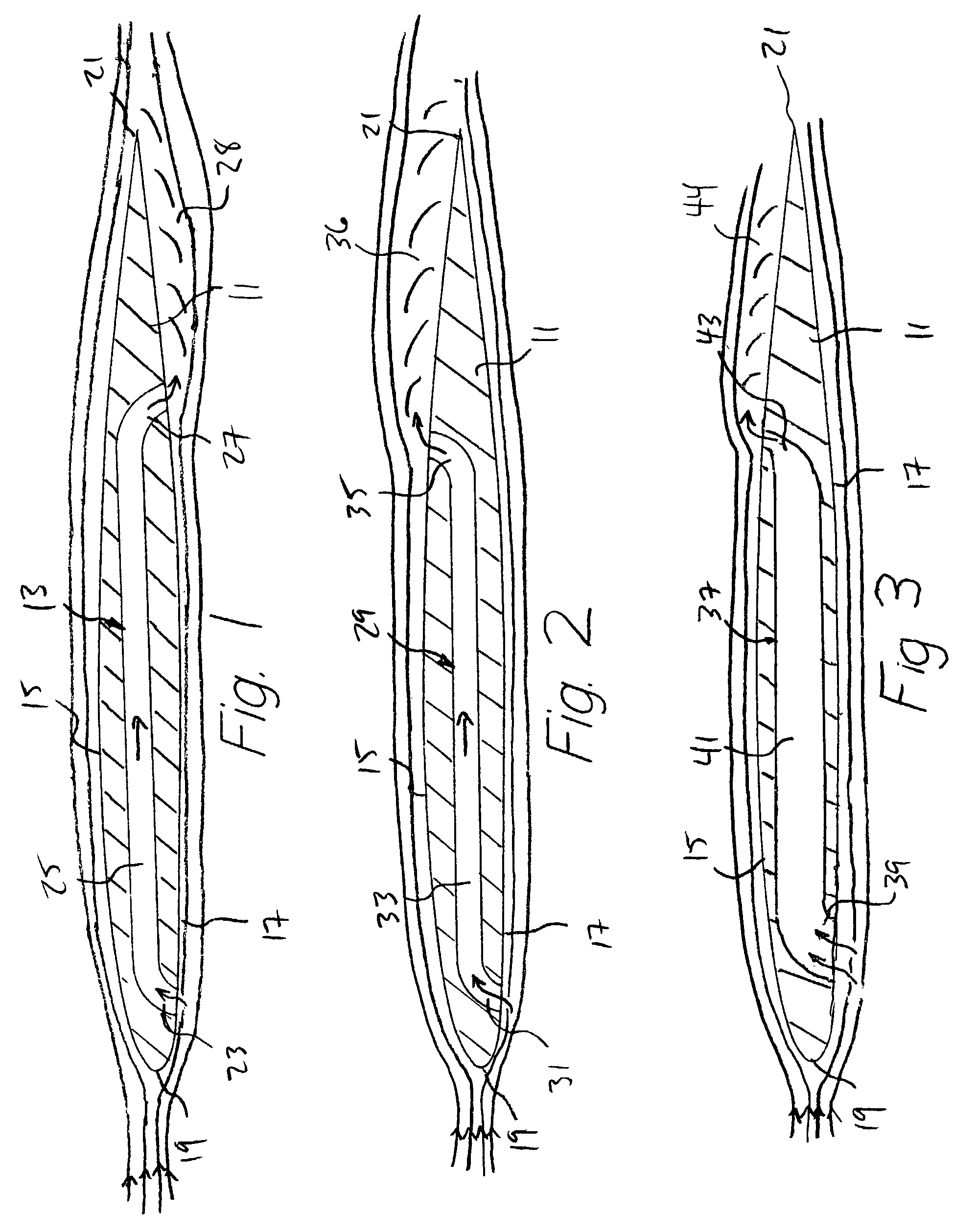
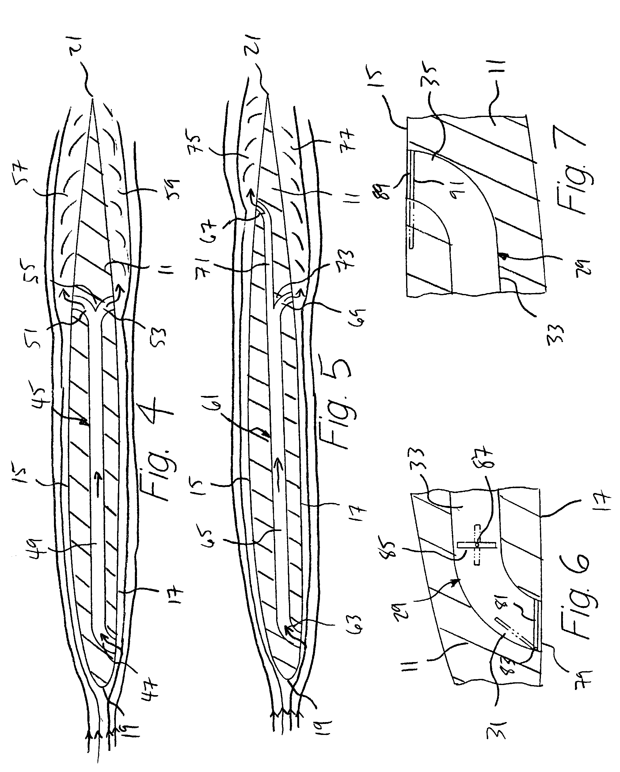
[0028]the invention is shown in FIG. 2. Spoiler 29 is formed in wing 11 and comprises inlet 31, passage 33, and outlet 35. Inlet 31 and passage 35 are formed like those in FIG.1, with inlet 31 intersecting lower surface 17. However, outlet 35 intersects upper surface 15 at a location aft of inlet 31, providing a pathway for communicating air from below lower surface 17 to above upper surface 15. As shown, inlet 31, passage 33, and outlet 35 have equal cross-sectional areas.

[0029]As described for the previous embodiment, a portion of the air flowing over lower surface 17 is diverted into inlet 31, and then the air flows through passage 33 and out of outlet 35. The air exits adjacent upper surface 15, causing the attached airflow over outlet 35 to become separated in flow area 36, causing the desired drag and resulting yaw moment. As with spoiler 13 (FIG. 1), small pitch and / or roll moments may be induced by the change in the amount of lift produced by wing 11.

third embodiment

[0030]A third embodiment, shown in FIG. 3, has a spoiler 37 in wing 11, spoiler 37 having an inlet 39 on lower surface 17, an internal passage 41, and a outlet 43 in upper surface 15 aft of inlet 39. Outlet 43 has a smaller cross-sectional area than inlet 39 and passage 41, and this decrease in cross-sectional area causes the air passing through outlet 43 to accelerate to a higher velocity than when it entered inlet 39. By accelerating the airflow at or near outlet 43, flow losses within spoiler 37 are reduced. The air exits outlet 43 adjacent upper surface 15 at high velocity, increasing the effectiveness in causing formation of a separated flow area 44 downstream of outlet 43. Separated flow area 44 causes drag on wing 11, and, as with spoiler 29, small pitch and roll moments may also be produced.

[0031]Though relatively small, the pitch and roll moments produced by spoilers 13 (FIG. 1), 29 (FIG. 2), and 37 (FIG. 3) may be undesirable if only a yaw moment is required. To effectivel...


PUM


Abstract

A wing for an aircraft has a passive jet spoiler for providing yaw control by increasing drag on the wing. The spoiler comprises an inlet located near the leading edge of a lower surface of the wing and at least one outlet formed on the lower surface or on an upper surface of the wing. An internal passage connects the inlet and each outlet for allowing air to pass from the inlet to the outlet. The air exits the outlets generally normal to the respective surface of the wing, causing a laminar flow to separate from the surfaces downstream of each outlet. The separated flow increases the drag on the wing, producing a yawing moment on the aircraft. Selective placement of the outlets on the upper and lower surfaces limits undesirable roll and pitch moments. Valves are provided for selectively controlling the amount of air passing through the spoiler.

Description

BACKGROUND OF THE INVENTION[0001]1. Field of the Invention[0002]The present invention relates generally to aerodynamic flight control of aircraft and relates specifically to passive jet spoilers used to create yaw moments.[0003]2. Description of the Related Art[0004]Wings for aircraft are constructed to have a longitudinal profile that produces lift as air flows across the upper and lower surfaces of the wing. The air flows with a greater velocity over the upper surface, producing a low-pressure area, and the high pressure below the wing pushes the wing upward. Ideally, the air flows across the wing in an attached, laminar stream adjacent a low velocity boundary layer, minimizing inherent drag and maximizing lift of the wing for a given airspeed. When the boundary layer becomes separated, or detached, from a portion of the wing, the flow becomes turbulent, and the wing is said to “stall” in that area. This increases drag and reduces lift.[0005]It is known in the art that this separa...

Claims


Application Information

Patent Timeline
IPC IPC(8): B64C21/02B64C15/14
CPCB64C15/14
Inventor MCCLURE, PAUL D.
Owner LOCKHEED MARTIN CORP
Why Eureka
Try Eureka