Air duct for supplying ambient air in an aircraft

a technology for air ducts and aircraft, which is applied in the direction of air intakes of naca type, energy-saving board measures, power plants of aircraft, etc., can solve the problems of particularly low drag, and achieve the effects of not excessively increasing the drag caused by air inlet, increasing drag, and increasing momentum

Active Publication Date: 2014-05-13
AIRBUS OPERATIONS GMBH
View PDF46 Cites 17 Cited by
  • Summary
  • Abstract
  • Description
  • Claims
  • Application Information

AI Technical Summary

Benefits of technology

[0016]In the third position of the flow control flap the first surface portion of the flow control flap is aligned in the region of the air inlet preferably at an angle of ca. 10° to the aircraft outer skin portion surrounding the air inlet. A flow control flap that is shaped and disposed in such a way that the first surface portion in the third position of the flow control flap forms an angle of ca. 10° with the aircraft outer skin portion surrounding the air inlet, on the one hand, enables the opening of a large flow cross section of the air inlet while, on the other hand, not excessively increasing the drag caused by the air inlet.
[0017]The flow control flap of the air duct according to the invention is further preferably so designed and disposed that in the third position of the flow control flap an edge of the flow control flap, for example an edge formed by the first and the second surface portion of the flow control flap, projects into an air flow flowing around the aircraft. Air may consequently be conveyed with a higher momentum from the boundary layer into the air duct. Although this leads to increased drag, the air-mass flow control range is markedly extended.

Problems solved by technology

When the flow control flap is situated in its second position, it generates particularly low drag.

Method used


Image

  • Air duct for supplying ambient air in an aircraft
  • Air duct for supplying ambient air in an aircraft
  • Air duct for supplying ambient air in an aircraft

Examples


Embodiment Construction

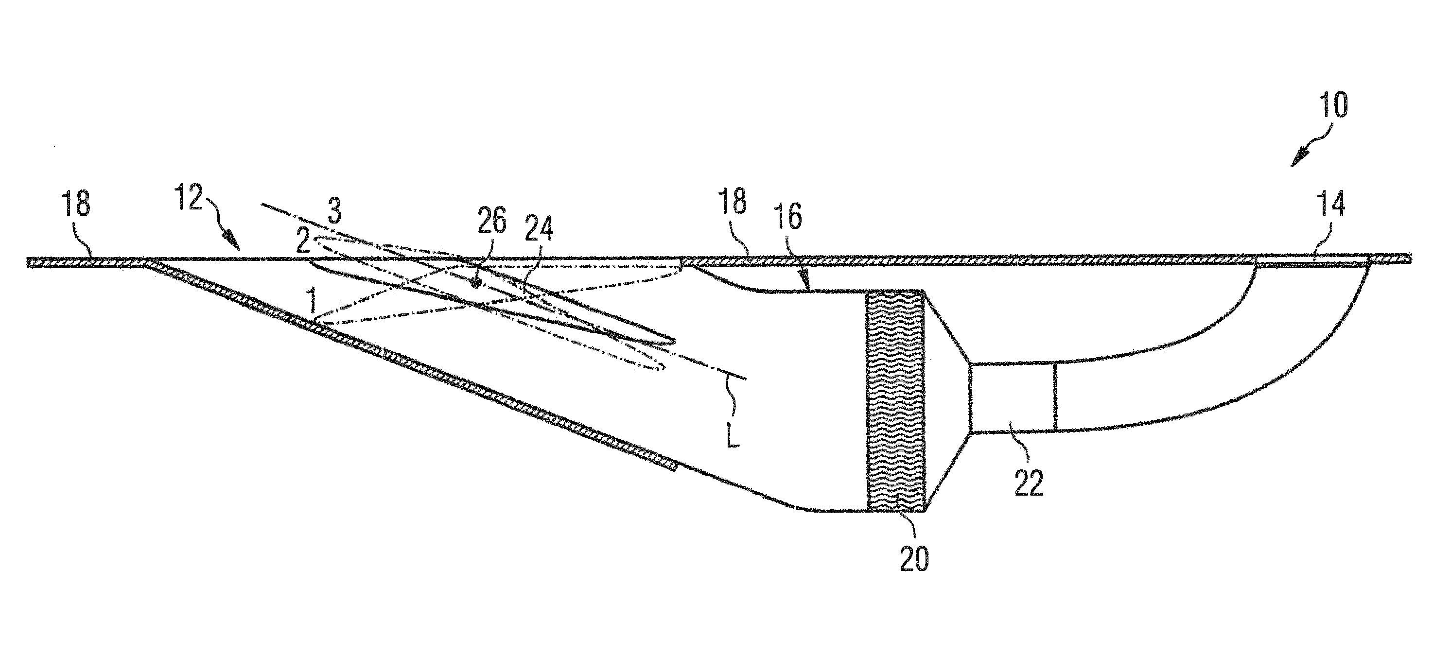
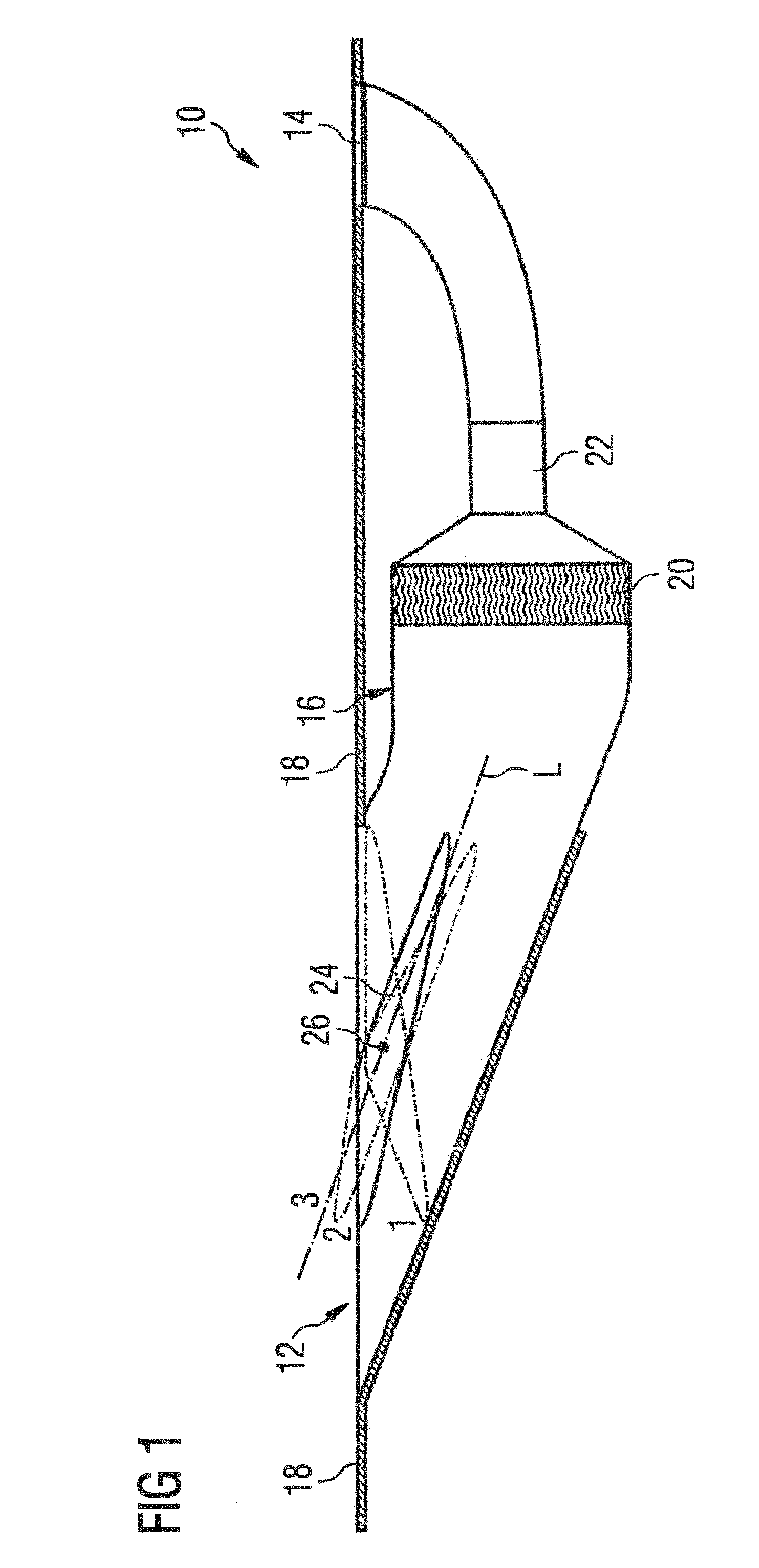
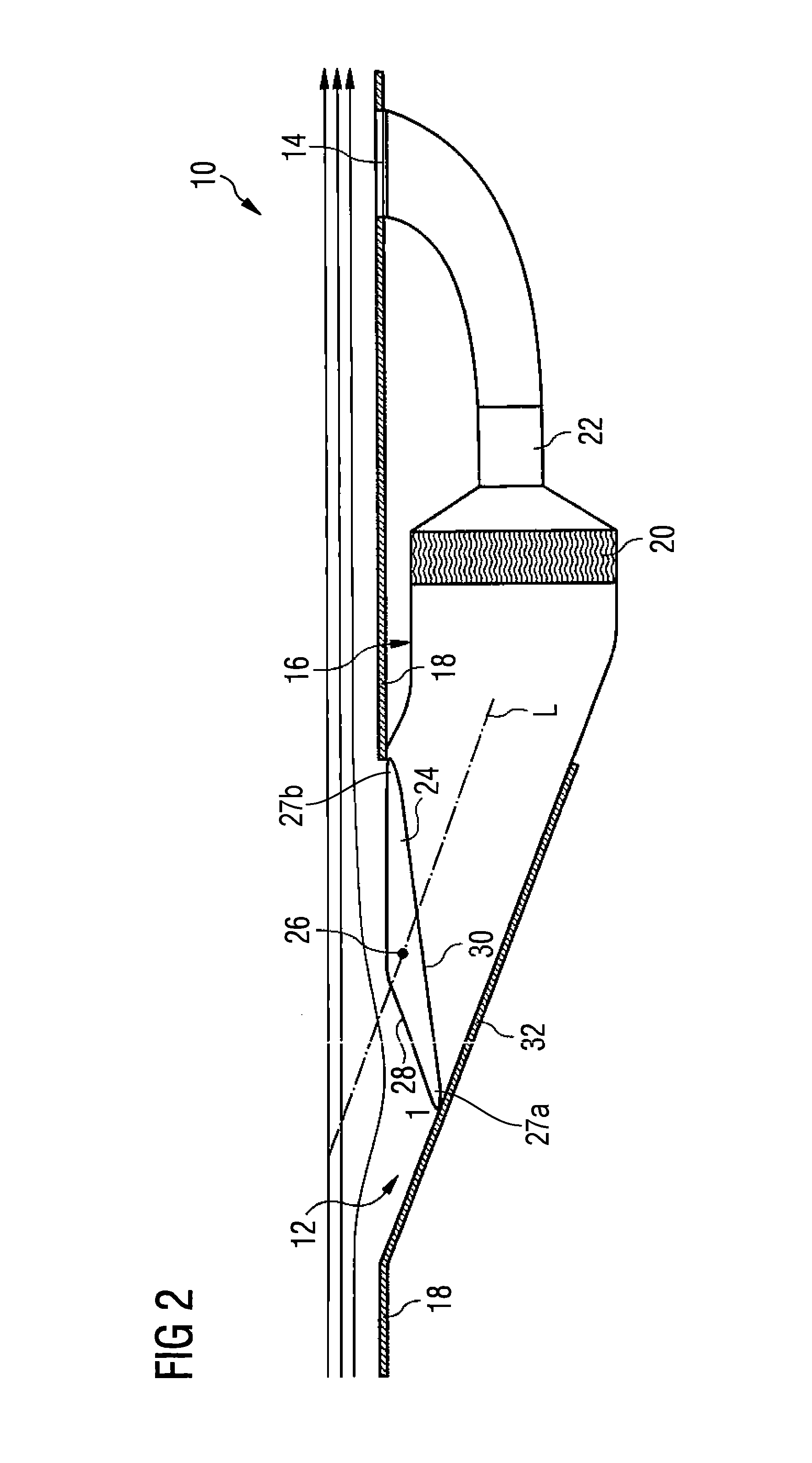
[0031]An air duct 10 that is shown in FIGS. 1 to 5 comprises an air inlet 12 as well as a flow duct portion 16 that extends downstream of the air inlet 12 as far as an air outlet 14. The air inlet 12 is integrated into a skin of an aircraft equipped with the air duct 10 and is consequently surrounded by a corresponding portion 18 of the aircraft outer skin. The air duct 10 is used to supply ambient air to a heat exchanger 20 disposed in the flow duct portion 16.

[0032]During cruising of the aircraft equipped with the air duct 10, the ambient air flowing around the aircraft outer skin flows through the air inlet 12 into the flow duct portion 16 and through the heat exchanger 20. During ground operation of the aircraft, on the other hand, a blower 22 ensures that sufficient ambient air is fed through the air inlet 12 and the flow duct portion 16 to the heat exchanger 20. In the embodiment of the air duct 10 shown in FIGS. 1 to 5 the blower 22 is disposed downstream of the heat exchange...


PUM


Abstract

An air duct for supplying ambient air in an aircraft includes an air inlet, a flow duct portion and a feed device that is devised to feed ambient air through the air inlet and the flow duct portion. A flow control flap closes the air inlet in a first position, releases a first flow cross-section of the air inlet in a second position and releases a larger second flow cross-section of the air inlet in a third position. The flow control flap is designed to not increase drag significantly in the second position while still enabling flow through the flow duct portion, while increasing drag to increase air fow through the flow duct portion in the third position.

Description

[0001]This application claims priority to PCT Application No. PCT / EP2009 / 004513, filed on Jun. 23, 2009 under Section 371 and / or as a continuation under Section 120, which claims priority to German Application No. 10 2008 030 399.2 and U.S. Provisional Application No. 61 / 075,814 both filed on Jun. 28, 2008.TECHNICAL FIELD[0002]The invention relates to an air duct for supplying ambient air in an aircraft.BACKGROUND[0003]Air ducts used in modern aircraft to supply ambient air to various systems situated on board the aircraft are conventionally configured as ram-air ducts having an air inlet and a diffuser. During cruising of the aircraft ambient air flows through the air inlet into the ram-air duct. In the diffuser, because of the slowing-down of the air flow, some of the dynamic pressure of the ambient air flow is converted to static pressure. As a result there arises in the ram-air duct a static pressure that is higher than the ambient pressure, the so-called ram pressure that ensur...

Claims


Application Information

Patent Timeline
Patent Type & Authority Patents(United States)
IPC IPC(8): B64D13/00
CPCB64D13/00B64D2241/00Y02T50/56Y02T50/50
Inventor KASTELL, DIRKROERING, SEBASTIANNORIEGA, WILSON WILLY CASAS
Owner AIRBUS OPERATIONS GMBH
Why Eureka
Try Eureka