Eureka AIR delivers breakthrough ideas for toughest innovation challenges, trusted by R&D personnel around the world.

Dumpster with a moveable false floor and method of collecting trash using the same

a technology of false floor and dumper, which is applied in the field of dumper, can solve the problems of dumper shaking, dumpster shaking, and dislodging adhesion of trash

Active Publication Date: 2015-02-03
NEXT MILLENNIUM DUMPSTERS
View PDF5 Cites 6 Cited by
  • Summary
  • Abstract
  • Description
  • Claims
  • Application Information

AI Technical Summary

Benefits of technology

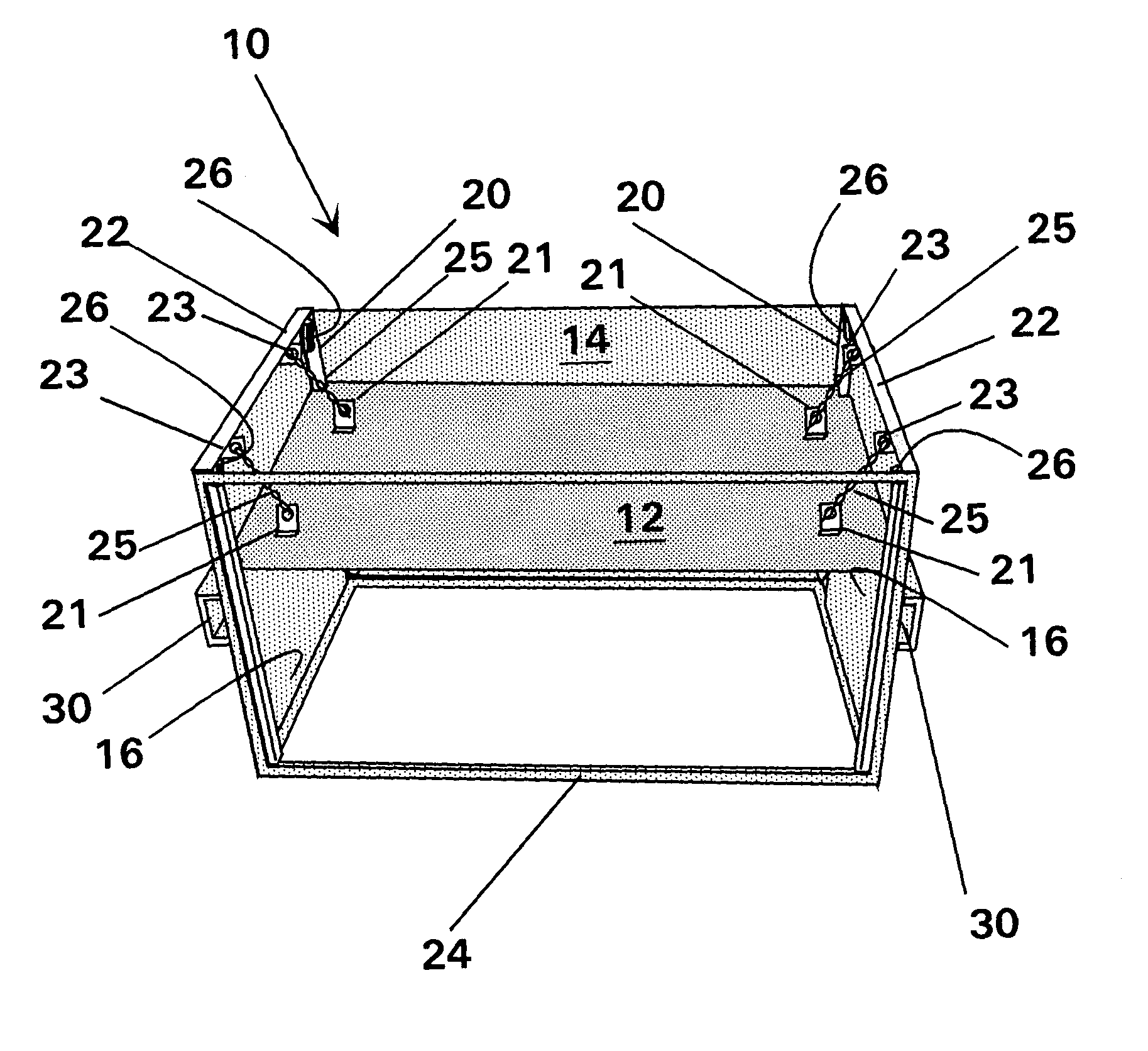
[0011]The invented dumpster comprises a walled container with a moveable false floor. The moveable false floor has a planar member having a plurality of upper coupling elements on a lower side of the planar member. There are also a plurality of lower coupling elements fixedly attached to the dumpster proximate to the bottom; and a restraining means. The restraining means comprises a plurality of connecting elements, where a connecting element is attached to an upper coupling element and a lower coupling element. The restraining means provides the moveable false floor freedom to fall a predetermined length toward the top opening, pushing out trash when the dumpster is tilted toward an inverted orientation. Upon reaching the predetermined length, the restraining means abruptly stops the falling floor, causing the dumpster to shake, which dislodges adhered trash. When the dumpster is returned to an upright orientation, the floor returns to the bottom of the dumpster. The moveable false floor eliminates the need for shaking and banging the dumpster with the hydraulic lifting-tilting system. Normally, there are at least four upper coupling elements on a lower side of the planar member, and four lower coupling elements fixedly attached to the dumpster proximate to the bottom, where a pair of upper and lower coupling elements are connected by a connecting element.
[0012]The restraining means has a collapsible member such as a chain, a telescoping rod, a pneumatic cylinder, a hydraulic cylinder, a cable, a line, or a combination thereof. The preferred collapsible member is a chain is strong, durable, easy to attach to a coupling element, inexpensive, and the length can be easily adjusted to a predetermined length. A chain is substantially inelastic, and so when it is fully extended it produces a finite abrupt stop to the downward movement of the moveable false floor, which in turn causes the dumpster to shake, dislodging adhered trash. If the invented dumpster is shaken using the hydraulic lifting-tilting system the movable floor amplifies the shaking and banging. The invented dumpster preferably further comprises a plurality of stops that prevent the moveable false floor from impinging lower coupling elements. The stops can have a dampening means that slowly stop the movement of the false floor when it returns to the bottom of the dumpster. The disclosed dumpster can be further comprised of a guiding means, which maintains the moveable false floor aligned substantially perpendicular to a sidewall of the dumpster, and delays movement by the false floor until the dumpster is approaching a fully inverted orientation. The advantage of delaying movement by the false floor until the dumpster is approaching a fully inverted orientation is that entire floor will fall the full predetermined length over a shorter time period, and will have higher a momentum, and therefore produce greater shaking and banging. An example of the there is a plurality of vertical longitudinal rails and intersecting slidable members. Most dumpsters also have a covering lid that closes over the top opening, that opens when the dumpster is inverted.

Problems solved by technology

Upon reaching the predetermined length, the restraining means abruptly stops the falling floor, causing the dumpster to shake, which dislodges adhered trash.
A chain is substantially inelastic, and so when it is fully extended it produces a finite abrupt stop to the downward movement of the moveable false floor, which in turn causes the dumpster to shake, dislodging adhered trash.

Method used


Image

  • Dumpster with a moveable false floor and method of collecting trash using the same
  • Dumpster with a moveable false floor and method of collecting trash using the same
  • Dumpster with a moveable false floor and method of collecting trash using the same

Examples


Embodiment Construction

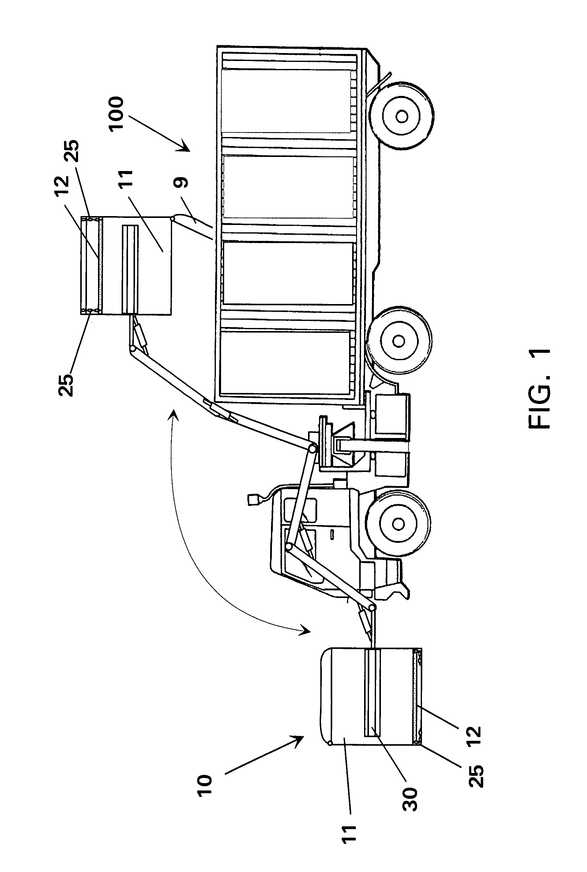
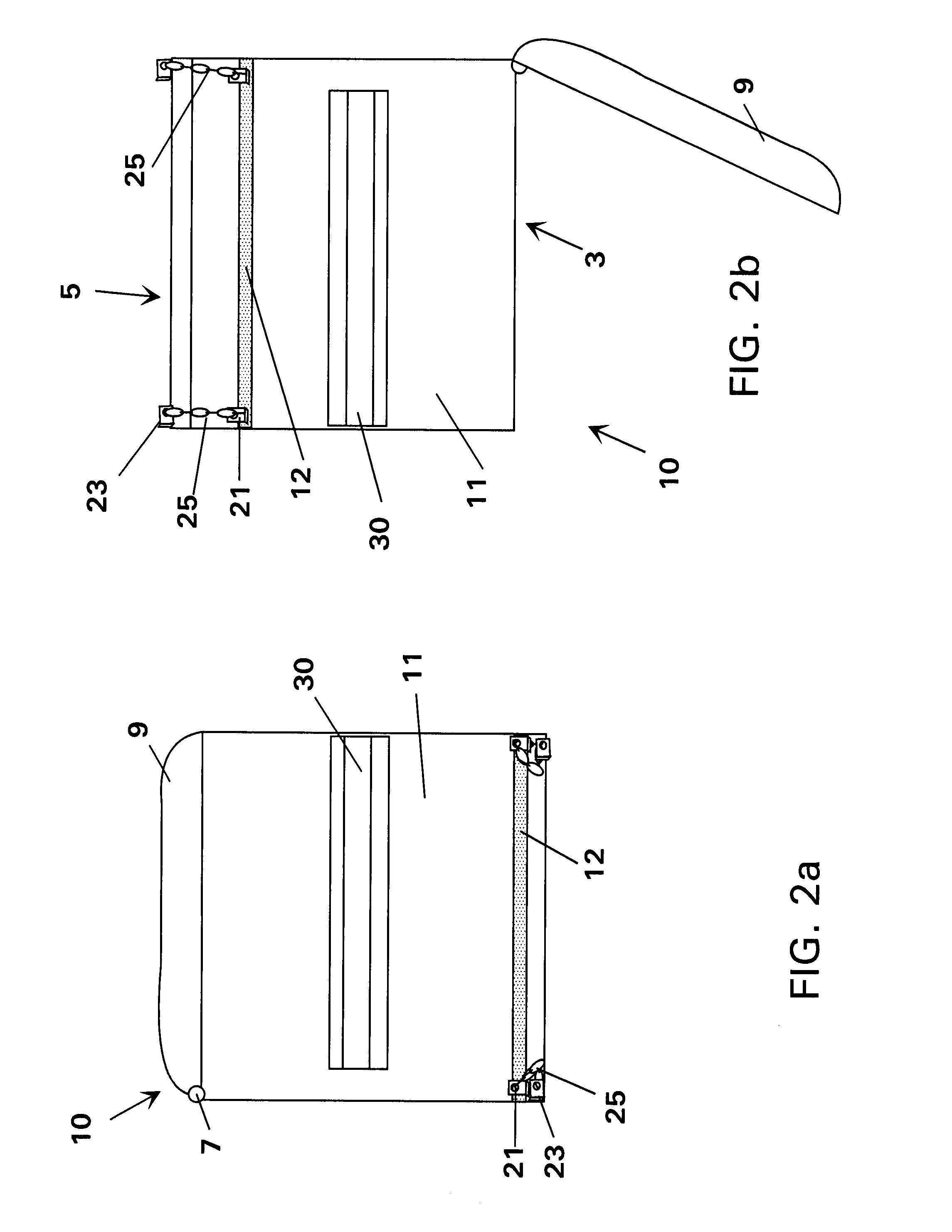
[0021]Referring now to the drawings, and particularly to FIG. 1, FIG. 2a and FIG. 2b, the invented dumpster 10 is a walled container 11 with a moveable false floor 12. The illustrated dumpster 10 has a covering lid 9 that is hinged 9, so that when the dumpster is tilted to an inverted orientation the lid opens exposing a top opening 3 as illustrated in FIG. 2b. The illustrated dumpster has forklift channels 30 that receive and are engaged by forks on a trash collection truck 100 fitted with a hydraulic lifting-tilting system. The invented dumpster has a moveable false floor 12 comprised of a planar member that substantially forms the cross-sectional area of the floor. Attached or otherwise apart of the planar member are a plurality of upper coupling elements 21, on a lower side of the planar member (moveable false floor 12). A plurality of lower coupling elements 23 are fixedly attached to the dumpster 10 proximate to the bottom 5. There is a restraining means comprised of a plurali...


PUM

PropertyMeasurementUnit
angleaaaaaaaaaa
lengthaaaaaaaaaa
distanceaaaaaaaaaa

Abstract

A dumpster having a moveable false floor which moves from a bottom of the dumpster toward a top opening when the dumpster is tilted to a substantially inverted orientation during collection of trash. The moveable false floor has freedom to move a predetermined length toward the top opening, where upon reaching the predetermined length a restraining device abruptly stops the floor causing the dumpster to shake dislodging adhered trash. Upon being returned to an upright orientation the moveable false floor moves back to the bottom.

Description

CROSS REFERENCE TO RELATED PATENT APPLICATIONS[0001]This application claims the benefit of the earlier filed provisional patent application filed on Jun. 6, 2006, bearing the Ser. No. 60 / 811,266.FIELD OF THE INVENTION[0002]The present invention relates to trash collection receptacles, and more particularly to a dumpster that empties quickly without the need of shaking or banging the dumpster using the hydraulic lifting-tilting system.BACKGROUND OF THE INVENTION[0003]Dumpsters and other trash receptacles are typically unloaded using large trash collection trucks with hydraulic lifting-tilting systems that lift and tilt the dumpster to an inverted position. In the tilted position the trash is no longer supported by the dumpster's floor, and a portion of the trash is pulled by gravity into the bay of the trash collection truck through the collection port. Even though the dumpster is inverted, a residual portion of trash is retained therein, adhered to the sidewalls and rim of the dumps...

Claims


Application Information

Patent Timeline
Patent Type & Authority Patents(United States)
IPC IPC(8): B65D43/12B65D83/00B65D43/20B65D1/24B65D1/36B65G65/34B65G65/04B65F3/02B65B69/00B65B21/02B67D7/60G01F11/10B65G65/44A45D24/22B67D7/84B65D8/06B65D8/04B65D6/28B65D85/00B65D57/00B65D25/04B65F1/12
CPCB65F1/122B65F1/12Y10S220/908Y10S206/804Y10S206/817Y10T29/53
Inventor GARAGIOLA, TONY
Owner NEXT MILLENNIUM DUMPSTERS
Why Eureka
Eureka Blog
Learn More