Stabilizing device

a stabilizing device and a technology for firearms, applied in the direction of mechanical equipment, other domestic objects, machine supports, etc., can solve the problems of inability of the shooter to accurately align the firearm with the target and maintain the alignment, so as to reduce or eliminate reduce the vibration of an object, and facilitate the operation of the object. more accurate

Active Publication Date: 2006-12-05
AOA PRODN LLC
View PDF17 Cites 73 Cited by
  • Summary
  • Abstract
  • Description
  • Claims
  • Application Information

AI Technical Summary

Benefits of technology

[0008]The present invention relates to a stabilizing device for reducing or eliminating the vibration in an object to allow for easier and more accurate operation of the object. In one (1) embodiment, the stabilizing device reduces vibration in the object caused by the positioning of the object on a vibrating surface. In another embodiment, the stabilizing device reduces vibration in the object caused by operation of the object. The stabilizing device includes an object bracket, legs, side arms and front arms. The legs and arms move the vibrations away from the object bracket and the object and eliminate or reduce the vibrations. The object is intended to be secured to the top side of the object bracket. In one (1) embodiment, a top plate is pivotably secured to the top side of the object bracket and the object is secured to the top plate. The top plate allows for additional positioning of the object after the stabilizing device is positioned on the ground. The legs extend outward from the object bracket and are intended to be positioned on the vibrating surface. The legs can be pivotably connected to the object bracket to enable the legs to be moved into a folded position when the stabilizing device is not in use. In one (1) embodiment, the longitudinal axes of the legs are perpendicular to the longitudinal axis of the object bracket and the object. The side arms are mounted on the object bracket and extend outward from the object bracket essentially perpendicular to the longitudinal axis of the object bracket and the object. The front arms are mounted on the front of the mounting bracket so that the longitudinal axes of the front arms are parallel to the longitudinal axis of the object bracket and the object. In the embodiment where the object is secured to a pivotable top plate, the front arms are also connected to the pivotable top plate. The legs include a core surrounded by damping material. The legs can be constructed from a variety of similar or different damping units. The damping units are preferably interchangeable so that the types of damping units can be varied depending on the object and the vibration to be damped. The side arms also have a core surrounded by damping material. The side arms could be constructed of a single damping unit. The front arms also include a center rod surrounded by damping material. The damping material of the front arms is spaced in front of the bracket. The damping characteristics of the front arms could be accomplished by a single damping unit. The damping characteristics of the legs, side arms and front arms can be adjusted by selecting damping material having different damping characteristics depending on the type of object to be used with the stabilizing device and the type of vibrations to be reduced or eliminated.
[0014]Still further, the present invention relates to a method for reducing vibration in a firearm positioned on a surface, which comprises the steps of: providing a stabilizing device including a bracket, legs having a first damping material connected to the bracket and side arms having second damping material connected to the bracket; connecting the firearm to the bracket; positioning the legs of the bracket on the surface; aligning the firearm with a target; and pulling a trigger of the firearm to hit the target wherein the stabilizing device reduces the vibration of the firearm to enable a more accurate shot.
[0015]Further still, the present invention relates to a method for reducing vibrations of a firearm positioned on a surface, which comprises the steps of: providing a stabilizing device including a bracket, legs connected to the bracket having first damping material, side arms connected to the bracket having second damping material and a forward arm connected to the bracket having third damping material; connecting the firearm on the bracket; positioning the legs of the stabilizing device on the surface; aligning the firearm with a target; and pulling a trigger of the firearm to shoot the target wherein the stabilizing device reduces vibration in the firearm to allow for a more accurate shot.
[0016]Finally, the present invention relates to a method for reducing vibration in an object positioned on a surface, which comprises the steps of: providing a stabilizing device including a bracket, legs having a first damping material connected to the bracket and side arms having second damping material connected to the bracket; connecting the object to the bracket; positioning the legs of the bracket on the surface; aligning the object with a target; and operating the object wherein the stabilizing device reduces the vibration in the object to enable a more accurate operation of the object.

Problems solved by technology

However, in the past, a shooter was unable to accurately align the firearm with the target and maintain the alignment when the firearm was resting on a vibrating surface.
The same problem occurs when other objects such as a camera are operated while positioned on a vibrating surface.

Method used


Image

  • Stabilizing device
  • Stabilizing device
  • Stabilizing device

Examples


Embodiment Construction

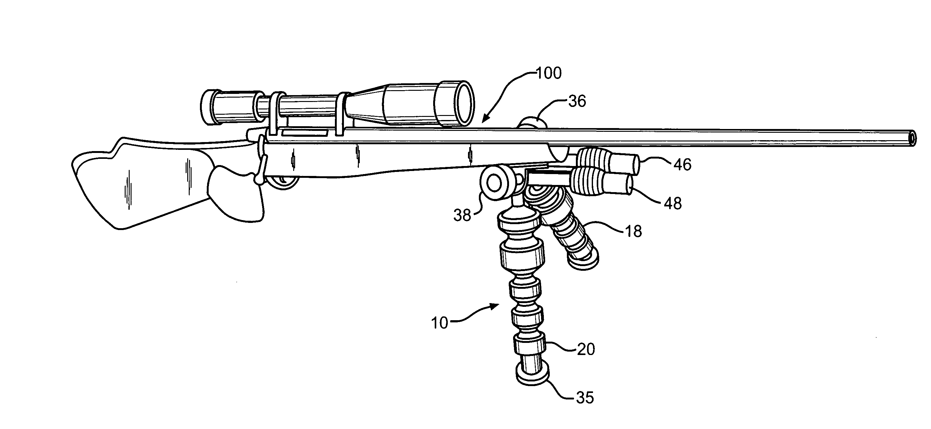
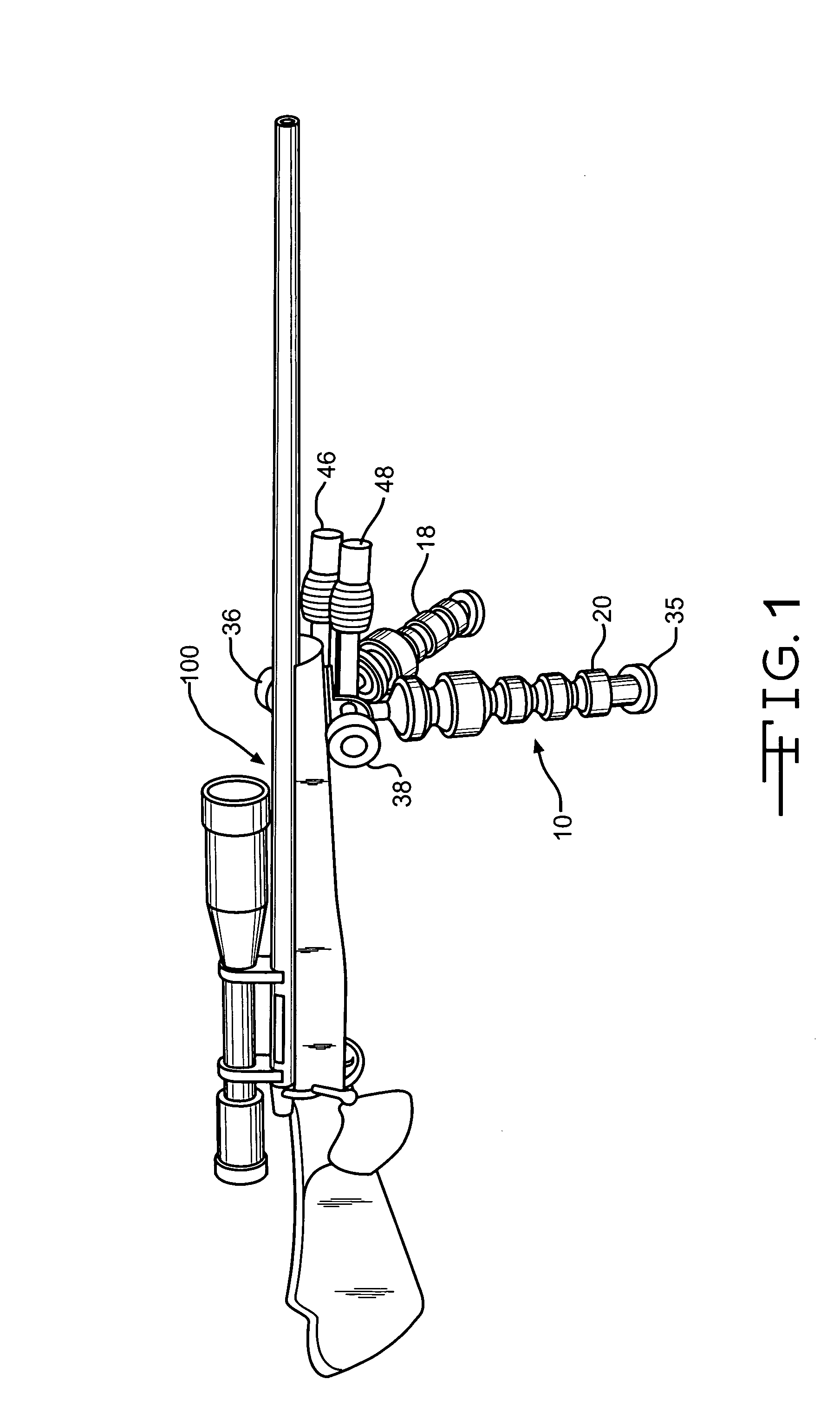
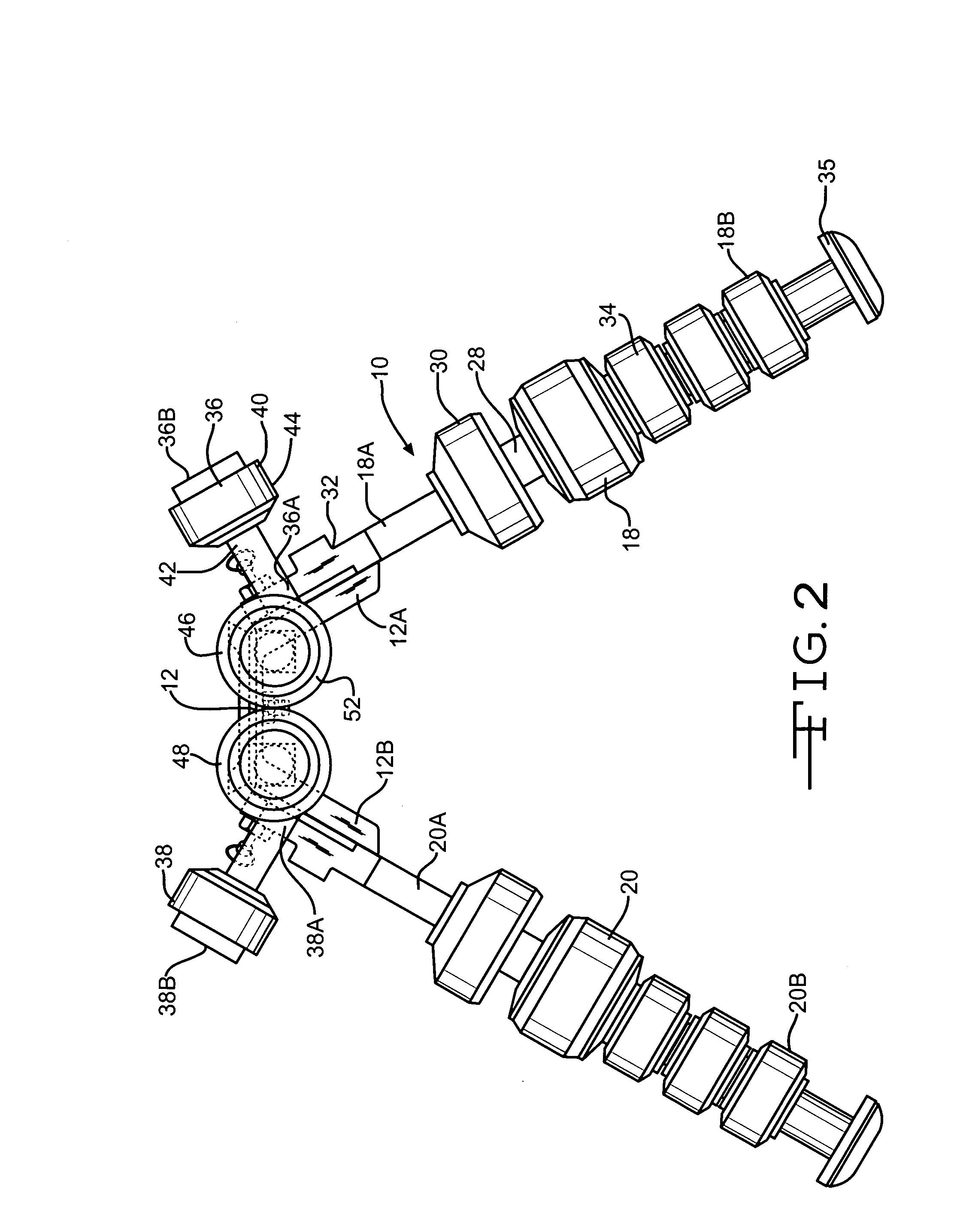
[0026]FIGS. 1 to 4 show the stabilizing device 10 of the present invention. The stabilizing device 10 includes an object bracket 12, legs 18 and 20, side arms 36 and 38 and front or forward arms 46 and 48. The object bracket 12 is positioned between the legs 18 and 20, side arms 36 and 38 and front arms 46 and 48 so that when the object 100 is mounted on the object bracket 12, the object 100 is positioned between the legs 18 and 20 and side arms 36 and 38. In one (1) embodiment, the bracket 12 has a pair of legs 12A and 12B mounted together at an angle to a center section 12C. In one (1) embodiment, a top plate 14 is pivotably mounted on the top side of the center section 12C of the bracket 12 such as to allow the object 100 connected to the top plate 14 to pivot while the object bracket 12 remains stationary (FIGS. 3 and 4). It is understood that the top plate 14 can be pivotably mounted on the center section 12C by any well known means. The top plate 14 can be pivotably connected ...


PUM


Abstract

A stabilizing device for reducing or eliminating the vibration in an object to allow for easier and more accurate operation of the object. The stabilizing device includes an object bracket, legs, side arms and front arms. The legs and arms move the vibrations away from the object bracket and the object and eliminate or reduce the vibrations. The legs and arms include a core surrounded by damping material. The damping characteristics of the legs, side arms and front arms can be adjusted by selecting damping material having different damping characteristics depending on the type of object to be used with the stabilizing device and the type of vibrations to be reduced or eliminated.

Description

CROSS-REFERENCE TO RELATED APPLICATION[0001]This application claims the benefit of provisional Application Ser. No. 60 / 456,219, filed Mar. 20, 2003.STATEMENT REGARDING FEDERALLY SPONSORED RESEARCH OR DEVELOPMENT[0002]Not ApplicableBACKGROUND OF THE INVENTION[0003](1) Field of the Invention[0004]The present invention relates to a stabilizing device for reducing the vibration in an object positioned on a surface. In particular, the present invention relates to a stabilizing device which reduces the vibration of a firearm caused by the movement or vibration of the surface on which the firearm is positioned.[0005](2) Description of the Related Art[0006]In today's conflicts, to be effective, a shooter must be able to accurately shoot from a variety of environments whether moving or stationary. However, in the past, a shooter was unable to accurately align the firearm with the target and maintain the alignment when the firearm was resting on a vibrating surface. The vibration of the surfa...

Claims


Application Information

Patent Timeline
Patent Type & Authority Patents(United States)
IPC IPC(8): F16M11/04
CPCF41A23/08F41A27/30F41C27/22
Inventor AUSTIN, DELBERT L.AUSTIN, RODNEY
Owner AOA PRODN LLC
Why Eureka
Try Eureka