Dry gas seal
- Summary
- Abstract
- Description
- Claims
- Application Information
AI Technical Summary
Benefits of technology
Problems solved by technology
Method used
Image

Examples
first embodiment
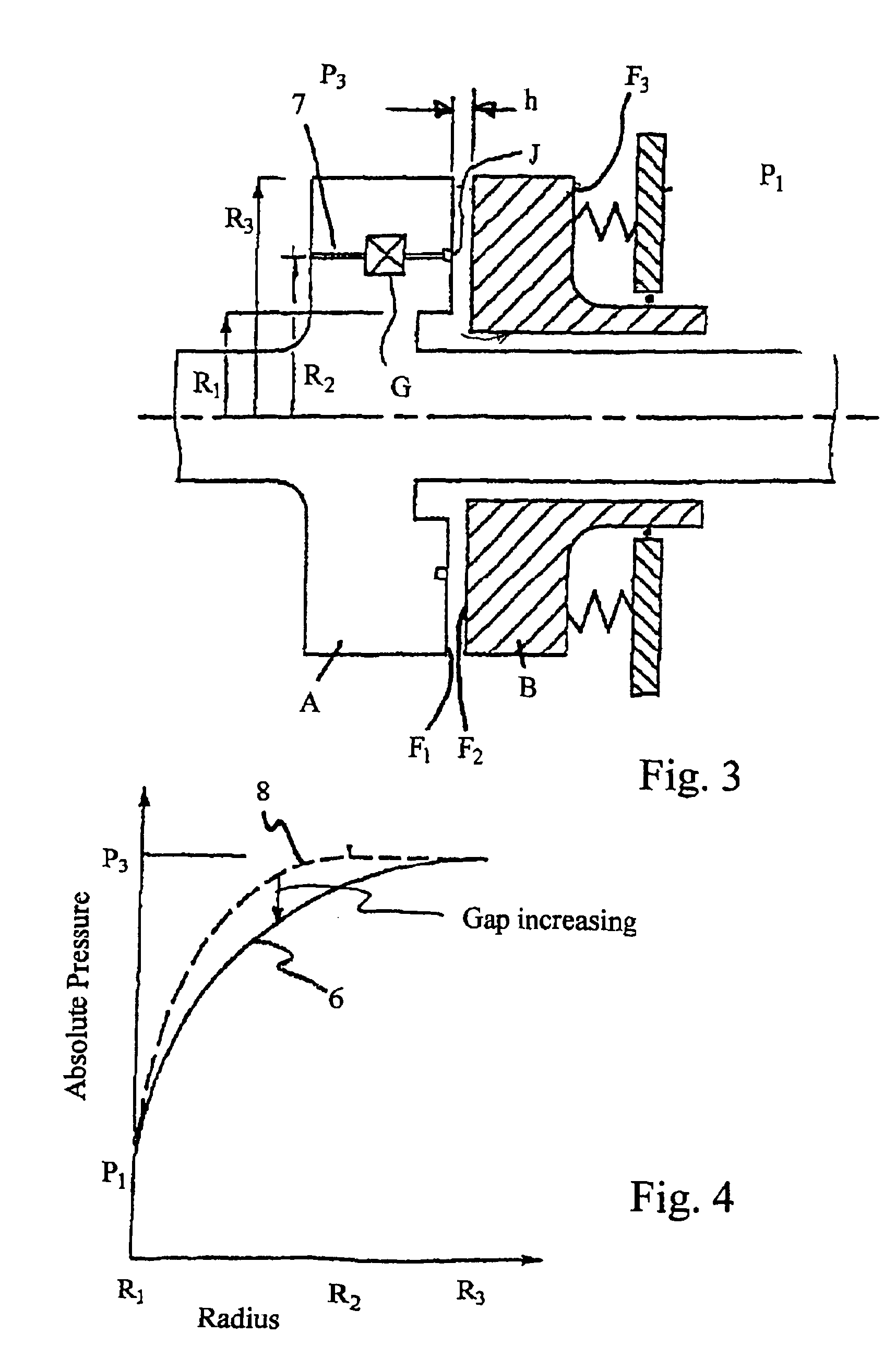
[0037]FIG. 3, which illustrates a seal assembly of the invention, is similar to FIG. 1, but with the addition, for illustrative purposes, of three or more arcuate, discontinuous distribution grooves J at radius R2, in the active face F1 of the member A and with the addition for illustrative purposes of a bleed channel 7 and an inline bleed flow throttle or resistance G associated with each arcuate groove J and which puts each groove J into communication with the high pressure P3 within the casing. In terms of physical principles, the distribution grooves J, channels 7 and the bleed resistances G might equally well be features of the stationary member B.
[0038]The significance of the distribution grooves J is to denote that the pressure on the concentric circle of radius R2 is constant, but only when the faces F1 and F2 are parallel. The pressures must become unequal when the faces are not parallel in order to produce the moment.
[0039]Two extreme conditions will now be considered with...
second embodiment
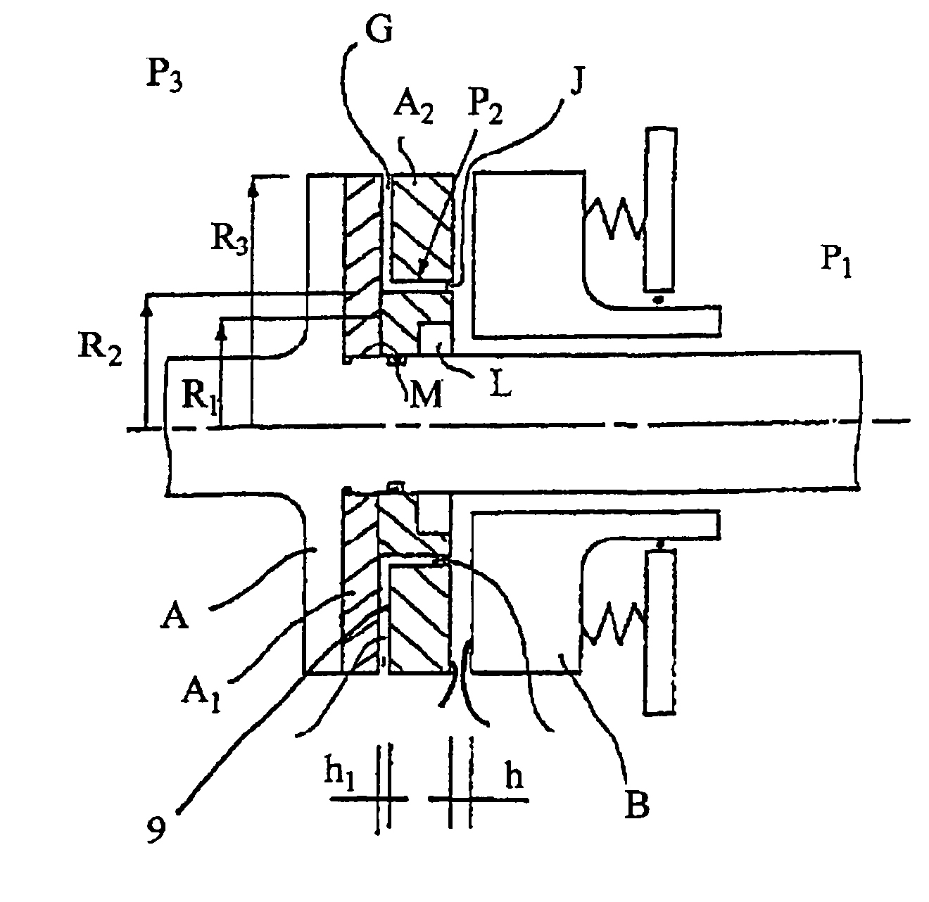
[0045]FIG. 7 is a cross-section of a seal assembly. The rotating member A is elaborated in FIG. 7 with the annular members A1 and A2. The faces of both members are parallel. Both faces of member A2 are lapped flat, as also is the right hand face of member A1. The facing faces of members A1 and A2 are held in contact by a screwed ring L. Leakage past the right hand surface of the flange A and the left hand surface of the member A1 is stopped by a seal M. The member A2 has formed in it distribution grooves as indicated at J and communicating holes as indicated at K, as described with reference to FIG. 6a. A bleed resistance or throttle referenced G in FIG. 7, comprises a generally radial depression 9 of depth h1 etched or otherwise produced in either the right hand face of member A1 or in the left hand face of member A2. The plan of such a depression 9 is illustrated in FIG. 6b. One such depression 9 is provided in alignment with each of the communicating holes K.
[0046]Attributes of t...
third embodiment
[0047]FIG. 8a, which is generally a repetition of FIG. 7, illustrates a seal assembly of the invention in which the bleed resistances G are formed in the right hand face of member A2 and take the form of a single depression per distribution groove J. In this embodiment the bleed resistances decrease as gap h increases because their effective depth is depression depth h1 plus gap h. Detritus from wear of the active faces might accumulate in the depressions of the bleed resistances and alter their value and furthermore wear of the right hand face of member A2 will reduce the value of h1 and if the wear should progress sufficiently the bleed resistances would be removed. A positive attribute of this embodiment is the absence of the member A1 of FIG. 7 and a simpler manufacture.
[0048]The principle which has been described of bleed resistances communicating with the high pressure side to distribution grooves in one or other of the active faces of a seal applies equally if the pressure P1...
PUM
 Abstract
Description
Claims
Application Information