
Vehicle front body structure

a front body and vehicle technology, applied in the direction of roofs, jet propulsion mounting, electric devices, etc., can solve the problems of fuel cell stack and fuel cell housing, unnecessarily broken fuel cell stack and unit box including fuel cell housing,

Active Publication Date: 2006-12-05
HONDA MOTOR CO LTD
View PDF19 Cites 119 Cited by
  • Summary
  • Abstract
  • Description
  • Claims
  • Application Information

AI Technical Summary

Benefits of technology

[0007]In view of the above circumstances, an object of the present invention is to provide a vehicle front body structure in which a unit box will not be unnecessarily broken during an offset collision.
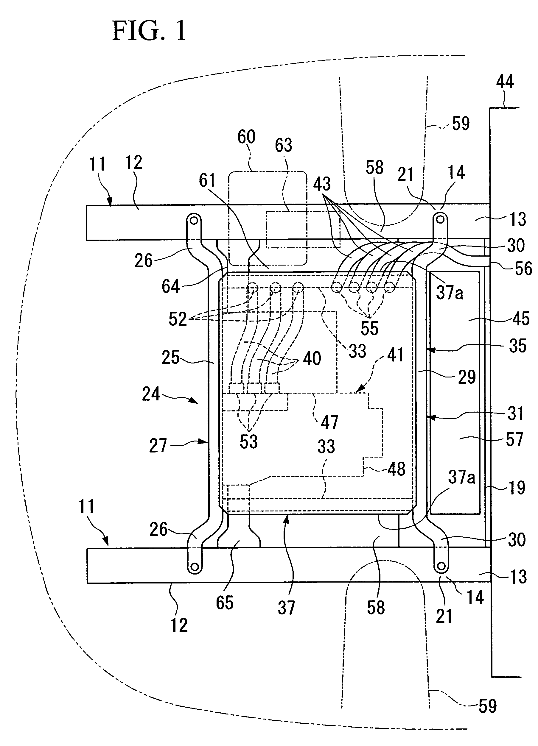
[0008]In order to achieve the above object, the present invention provides a vehicle front body structure including: a pair of front side frames each of which has, at a rear portion thereof, an easily deformable portion that is easily deformable during a collision; a support frame for mounting a unit box thereon, which has a pair of rear legs that are fixed to the easily deformable portions of the pair of front side frames, and a pair of front legs that are fixed to portions of the pair of front side frames, the portions being located in the front as viewed from the easily deformable portions, wherein displacement allowing spaces for allowing displacement of the unit box during a collision are provided near side portions of the unit box adjacent to the rear legs.
[0009]According to the vehicle front body structure as configured above, because the pair of rear legs of the support frame are fixed to the easily deformable portions of the front side frames, and the pair of front legs are fixed to portions of the front side frame located in the front as viewed from the easily deformable portion, when the easily deformable portion of one of the front side frames deforms during an offset collision in which an impact force in applied to one of the front side frames, the unit box supported by the support frame rotates about one of the front legs fixed to the other of the front side frames to which the impact force is not applied. As a result, displacement of the unit box near the front legs is restrained, and a portion of the unit box near the rear legs mainly moves laterally. This lateral displacement of the unit box is allowed by the displacement allowing space which is provided near the side portion of the unit box adjacent to the rear leg. Because the unit box is guided into the displacement allowing space as described above, the unit box is prevented from being broken.
[0011]According to the vehicle front body structure as configured above, because the space, which is located near the side portion of the unit box adjacent to the front leg, is made narrow, displacement of the unit box in the space is restrained; therefore, the rotation of the unit box about the front leg can be ensured.

Problems solved by technology

In the case of the above-mentioned vehicle front body structure, a fuel cell stack and a unit box including a fuel cell housing may be unnecessarily broken during such an offset collision.
Such a problem may also be encountered in the case in which the unit box may be of another type such as a control unit box.

Method used


Image

  • Vehicle front body structure
  • Vehicle front body structure
  • Vehicle front body structure

Examples


Embodiment Construction

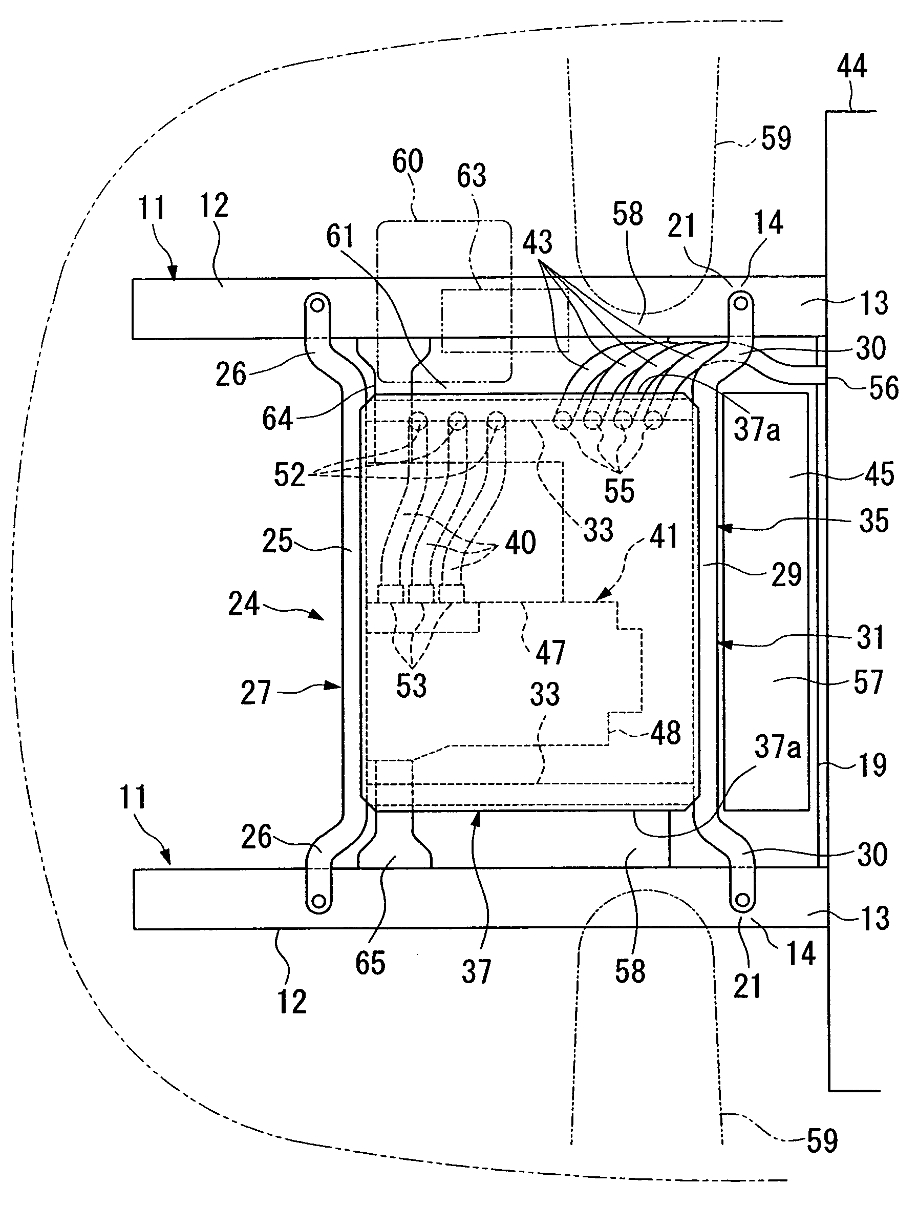
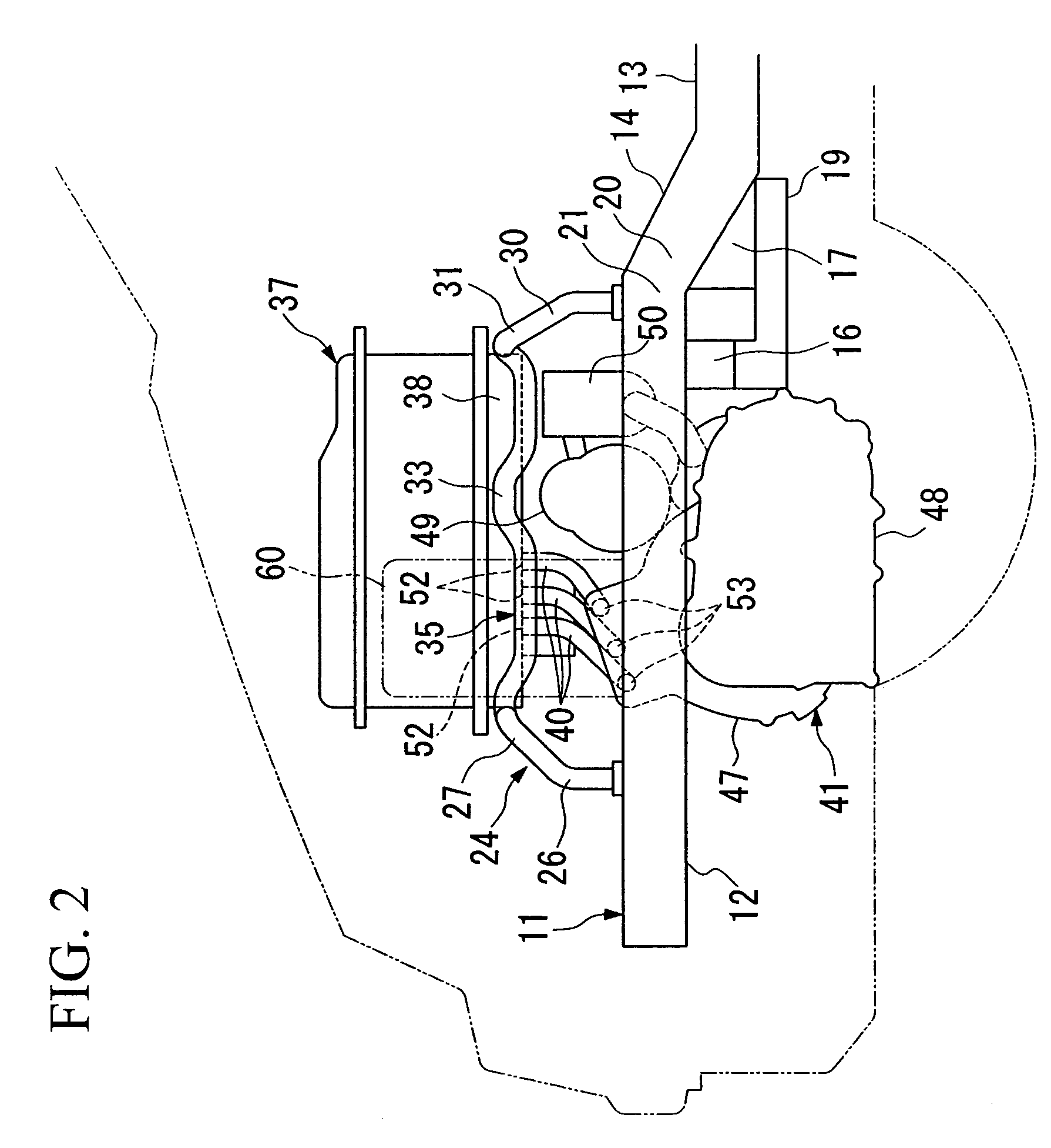
[0020]A vehicle front body structure according to an embodiment of the present invention will be explained below with reference to the appended drawings. In the following description, a longitudinal direction and a lateral direction are respectively defined on the basis of a plan view of a vehicle that travels in the longitudinal direction.

[0021]The vehicle front body structure according to the present embodiment is, more specifically, a vehicle front body structure for a fuel cell powered vehicle which is driven by a drive motor that is supplied with electrical power from a fuel cell stack.

[0022]As shown in FIGS. 1 to 3, in the front portion of a vehicle body, there are provided a laterally arranged pair of front side frames 11 as main structural body members, each of which extends in the longitudinal direction of the vehicle. Each of the front side frames 11 is formed in a stepped shape, and includes a front extending portion 12 which occupies a front portion of the front side fra...


PUM

PropertyMeasurementUnit
voltageaaaaaaaaaa
displacementaaaaaaaaaa
impact energyaaaaaaaaaa

Abstract

A vehicle front body structure includes a pair of front side frames each of which has, at a rear portion thereof, an easily deformable portion that is easily deformable during a collision, a support frame for mounting a unit box thereon, which has a pair of rear legs that are fixed to the easily deformable portions of the pair of front side frames, and a pair of front legs that are fixed to portions of the pair of front side frames, the portions being located in the front as viewed from the easily deformable portions. Displacement allowing spaces for allowing displacement of the unit box during a collision are provided near side portions of the unit box adjacent to the rear legs.

Description

BACKGROUND OF THE INVENTION[0001]1. Field of the Invention[0002]The present invention relates to a vehicle front body structure.[0003]Priority is claimed on Japanese Patent Application No. 2002-326810, filed Nov. 11, 2002, the content of which is incorporated herein by reference.[0004]2. Description of Related Art[0005]As an example of a vehicle front body structure, a structure is known, which includes front side frames which are formed so as to be deformed in an upwardly convex shape, and a fuel cell housing for holding a fuel cell stack disposed above the front side frames, which is also formed so as to be deformed in an upwardly convex shape. In the event of collision, in order to absorb impact energy, the front side frames and the fuel cell housing are intentionally made so as to bend, and the fuel cell is made so as to break apart (see, for example, Japanese Unexamined Patent Application, First Publication No. Hei 08-192639).[0006]In one type of head-on collision of a vehicle,...

Claims


Application Information

Patent Timeline
Patent Type & Authority Patents(United States)
IPC IPC(8): B62D7/22B60K1/04B60K8/00B62D25/20B60R16/02B62D21/15H01M8/04
CPCB60K1/04B60L3/0007B60L11/1877B60L11/1896B60L15/007B62D21/152B60K2001/0411Y02T10/705Y02T90/34B60L50/66B60L50/71Y02T10/64Y02T10/70Y02T90/40
Inventor KAWASAKI, SATOSHIFUKAZU, TOMOHIROHATTORI, HIROYUKI
Owner HONDA MOTOR CO LTD
Learn More