Display form having magnetically attachable parts

a technology of magnetic attachment and display form, which is applied in the direction of rod connection, dolls, instruments, etc., can solve the problems of heavier and more costly joints, and achieve the effects of reducing the leakage of magnetic force, facilitating dressing, and reducing the risk of slipping

Inactive Publication Date: 2006-12-05
NOA BRANDS AMERICA
View PDF39 Cites 25 Cited by
  • Summary
  • Abstract
  • Description
  • Claims
  • Application Information

AI Technical Summary

Benefits of technology

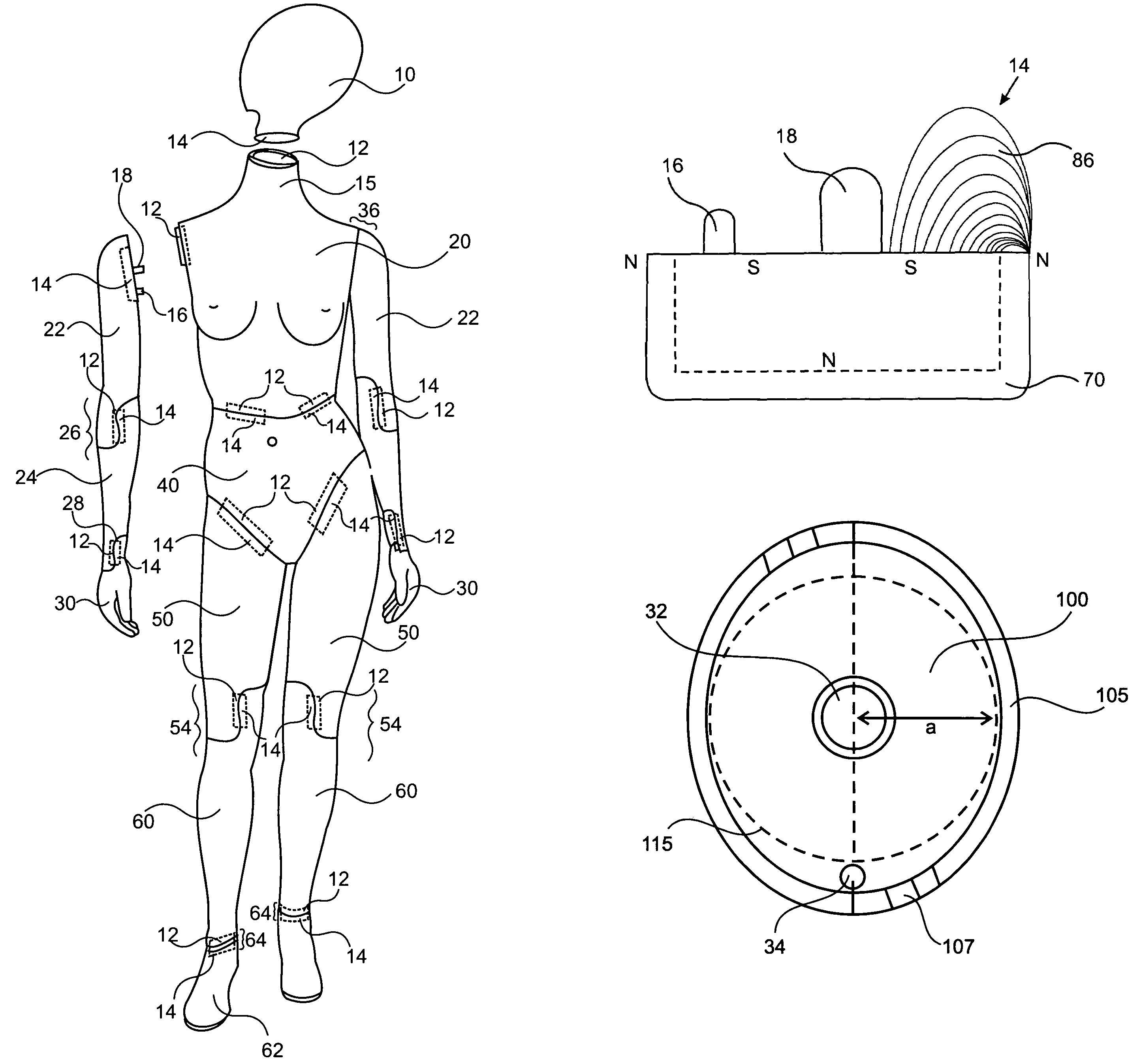
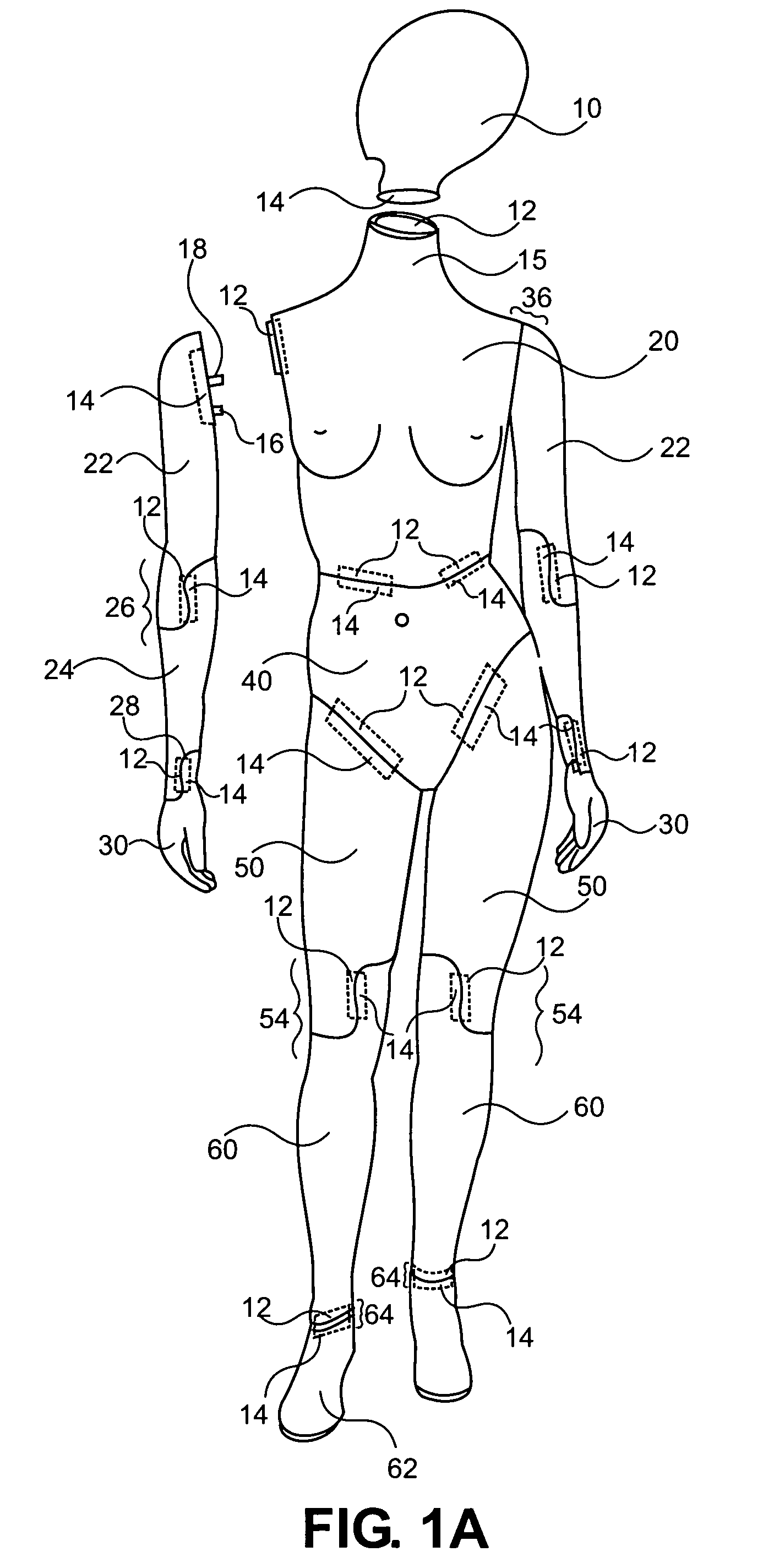
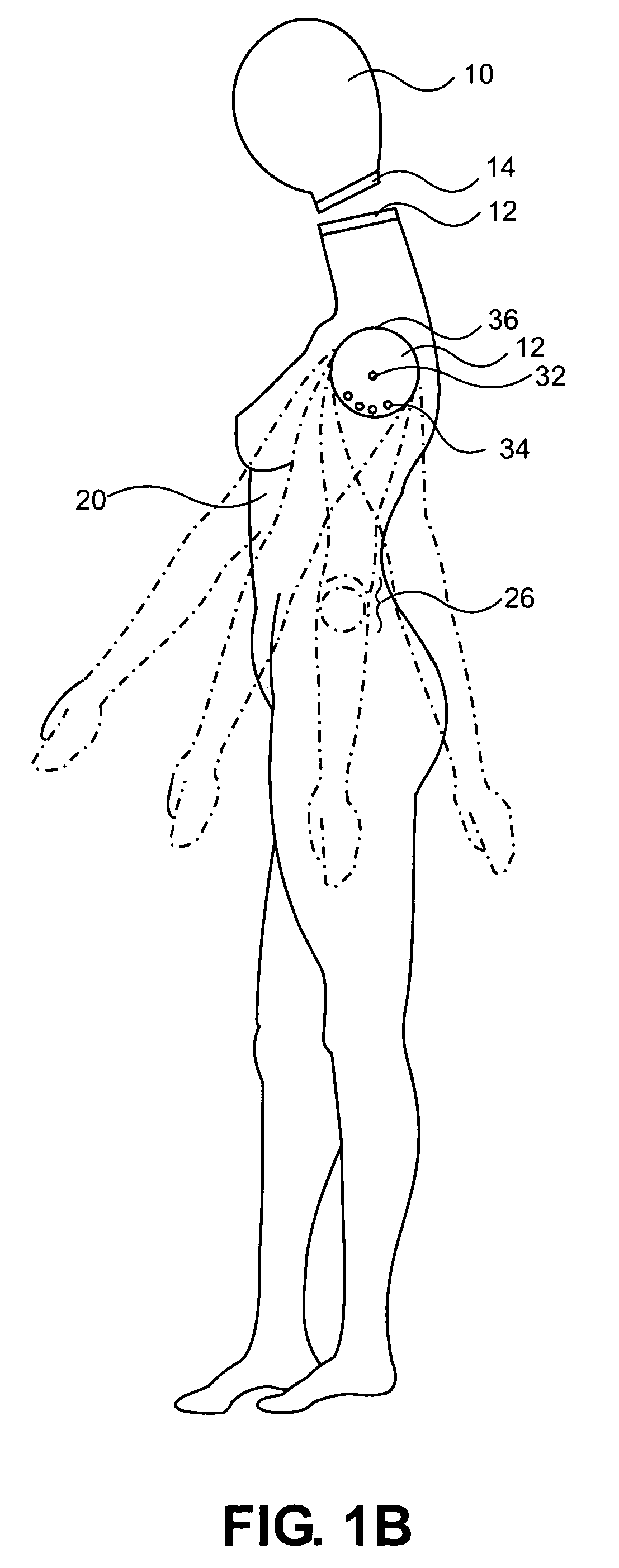
[0019]The manikins of this invention having magnetically attachable parts have the following advantages: If the manikin is knocked over, or if someone pulls on the attached part, it will come loose rather than breaking off; and the mating parts are self-seeking in use, so that they will come together in proper orientation even when being mated beneath clothes. Generally, manikins are dressed with arms removed, and the arms then have to be inserted and positioned inside the sleeves “blind,” without the dresser being able to see to align them properly. The self-seeking feature of the magnetic mating parts of this invention substantially aids in ease of dressing and provides significant time savings for manikin dressers.
[0020]In a preferred embodiment hereof, a cup magnetic assembly comprising a circular cup which serves as a pole piece is provided. It is believed that the cup shape focuses the magnetic energy toward the front (top edge of the cup), minimizing leakage of magnetic force. The cup need not be circular; it can also be square, rectangular, oval, polygonal, or other shapes. A magnetic material within the cup provides the magnetic force. Many magnetic materials are known to the art including strontium ferrite ceramic magnets, neodymium and samarium cobalt. To optimize performance and cost, combinations of known magnetic materials may be used, e.g., combinations of lower power magnets such as strontium ferrite ceramic, ferrite with higher power magnets such as neodymium or strontium cobalt, or either type with arnico or other medium power magnet.
[0021]The cup assembly allows the magnetic field to be forced to the outer edges of the cup to take full advantage of the magnets being used.

Problems solved by technology

Thicker pieces may be used, but will result in a heavier and more costly joint.

Method used


Image

  • Display form having magnetically attachable parts
  • Display form having magnetically attachable parts
  • Display form having magnetically attachable parts

Examples


example 1

[0074]The on-contact and depth-of-pull strengths of magnetic assemblies of this invention were tested and compared to those of conventional sandwich magnets using a gauss meter. FIGS. 9A and 9B show the points where the measurements were taken. FIG. 9A shows the magnetic assembly of this invention with the poles labeled N (north) and S (south). The asterisk 90, positioned about one-fourth inch from the center of the 2.5-inch-diameter magnetic assembly, indicates that the strongest depth-of-pull force was measured at this distance from the center. The circle 92 on the perimeter of the pole piece 70 indicates that the strongest on-contact force is measured at the perimeter. FIG. 9B shows a sandwich magnet of the prior art. The asterisk 94 indicates where the strongest depth-of-pull forces were measured. This point also corresponds to circle 96, the point where the strongest on-contact forces were measured. The magnet of this invention weighed 0.581 pounds. The sandwich magnet weighed ...

example 2

[0077]The on-contact and depth of pull strengths of a magnetic assembly as shown in FIGS. 8A and 8B were measured using a gauss meter, and are shown in Table 3. The strongest point on the magnet was measured at 3 / 32″ (± about 1 / 32″) from the center of the magnet. The depth-of-pull forces were measured at this same location. This magnetic assembly began to “seek home” at a distance of about ¾.″ The weight of the magnet was about 0.03 lb.

[0078]

TABLE 3Distance from MagnetNeodymium Cup AssemblyStrongest contact on Pole1500 gaussPieceStrongest Point on Magnet2990 gauss 1 / 32inch2800 gauss⅛inch2000 gauss¼inch1550 gauss½inch 680 gauss¾inch 338 gauss1inch 178 gauss


PUM


Abstract

Forms for display of clothing and the like with magnetically attachable parts are provided. The magnetic joints comprise a magnetic assembly with a depth-of-pull sufficient to cause the attachable part to begin to pull toward the form at a distance preferably greater than one-half inch, preferably about one inch. Preferably the magnetic assembly has a depth-of-pull of at least about 120 gauss at a distance of one inch. A metallic plate is arranged in mating configuration with the magnetic assembly. Mating pins may be provided, as well as indexing pins. If the manikin is knocked over, or if the attached part is pulled or bumped, it will come loose rather than breaking off; and the mating parts are self-seeking in use, so that they will come together in proper orientation even when being mated beneath clothes. A bump to the manikin sufficient to overcome the on-contact strength of the magnetic attachment may not result in detachment of the limb because of the depth-of-pull strength of the magnetic assembly. The indexing pins allow the limbs to be placed in a variety of positions.

Description

CROSS-REFERENCE TO RELATED APPLICATIONS[0001]This application is a continuation-in-part of U.S. application Ser. No. 09 / 771,431, filed Jan. 26, 2001, now U.S. Pat. No. 6,705,794 which claims priority from U.S. provisional application No. 60 / 178,187, filed Jan. 26, 2000, both of which are incorporated herein by reference to the extent not inconsistent herewith.BACKGROUND[0002]Forms or manikins to display clothing or other merchandise are models of complete human bodies or parts thereof, often of life-size proportions. It is difficult to dress such forms unless the limbs are detachable.[0003]U.S. Pat. No. 3,028,058 discloses a manikin with truncated legs, swiveling arms, and a detachable head. In manikins with removable parts, at least one leg is often made to be removable, arms are removable, and the torso may be made in two parts. Hands may also be detachable. Bayonet attachments are common means for attaching detachable limbs to forms, wherein a projection on the limb must be inser...

Claims


Application Information

Patent Timeline
Patent Type & Authority Patents(United States)
IPC IPC(8): A63H3/14D06C15/00F16C11/00F16D1/12F16G11/00A47F8/00F16C11/04
CPCA47F8/00A63H3/46G09B19/10G09B23/34F16C11/04Y10T403/32262Y10T403/18Y10T403/32983Y10T403/32426Y10T24/32Y10T403/74Y10S403/01
Inventor VARNER, RICHARDBARBER, JAMES D.TALARIC, JAMES
Owner NOA BRANDS AMERICA
Why Eureka
Try Eureka