Wind turbine with outer noise shell

a technology of wind turbines and towers, applied in the direction of liquid fuel engines, instruments, other chemical processes, etc., can solve the problems of re-design of existing structures, legal limitations on the permitted intensity of mean noise radiation, and disturbing sound developmen

Inactive Publication Date: 2006-12-05
GENERAL ELECTRIC CO
View PDF4 Cites 46 Cited by
  • Summary
  • Abstract
  • Description
  • Claims
  • Application Information

AI Technical Summary

Benefits of technology

[0012]The noise shell which at least partially surrounds the tower serves the purpose of absorbing the noise emitted from the tower and, therefore, results in a considerable reduction of the noise emission of the wind turbine. Thereby, the noise shell forms a kind of noise cladding, which is positioned at a distance from the outside of the tower, that is an air gap remains between the wall of the tower and the noise shell. Therefore, no direct transmission path for the noise exists between the tower and the noise shell, so that the noise cannot be transmitted from the tower to the noise shell as impact sound. The wall of the tower oscillates rather freely and emits these oscillations as noise like a tower not provided with a noise shell. The noise, which is normally widely emitted is, however, intercepted by the noise shell and absorbed.
[0013]This solution has the advantage that the oscillation characteristics of the tower wall are only marginally amended. The tower can be surrounded by the noise shell at a later date, provided that a noise reduction is required.
[0014]In one embodiment of invention the noise shell comprises an outer layer and a damping layer directed towards the tower. The damping layer leads to extensive absorption of the noise. In contrast, the outer layer serves as a stabilizer of the noise shell and protects the damping layer from the effects of the weather. For example, the outer layer can be formed of glass-fiber reinforced plastic or aluminium. Preferably, the noise shell is formed with a closed, waterproof outer layer.
[0014]In one embodiment of invention the noise shell comprises an outer layer and a damping layer directed towards the tower. The damping layer leads to extensive absorption of the noise. In contrast, the outer layer serves as a stabilizer of the noise shell and protects the damping layer from the effects of the weather. For example, the outer layer can be formed of glass-fiber reinforced plastic or aluminium. Preferably, the noise shell is formed with a closed, waterproof outer layer.

Problems solved by technology

During the operation of a wind turbine, sounds develop that can be found disturbing.
For technical systems there are legal limitations regarding the permitted intensity of a mean noise radiation.
However, this solution requires a re-design of the existing system.
The noise reduction achieved with these proposals often does not meet the legal requirements or are not justifiable for economical reasons.
Therefore, no direct transmission path for the noise exists between the tower and the noise shell, so that the noise cannot be transmitted from the tower to the noise shell as impact sound.
The noise, which is normally widely emitted is, however, intercepted by the noise shell and absorbed.
The damping layer leads to extensive absorption of the noise.

Method used


Image

  • Wind turbine with outer noise shell
  • Wind turbine with outer noise shell
  • Wind turbine with outer noise shell

Examples


Embodiment Construction

[0023]In the following it is referred to the presently preferred embodiments shown in the figures. Each embodiment merely serves as a more detailed exemplification of the invention and is not to be understood as limiting the invention. For example, the features shown in one of the embodiments can also be used in another embodiment or can be combined with features of other embodiments, in order to obtain further modified embodiments within the scope of the invention.

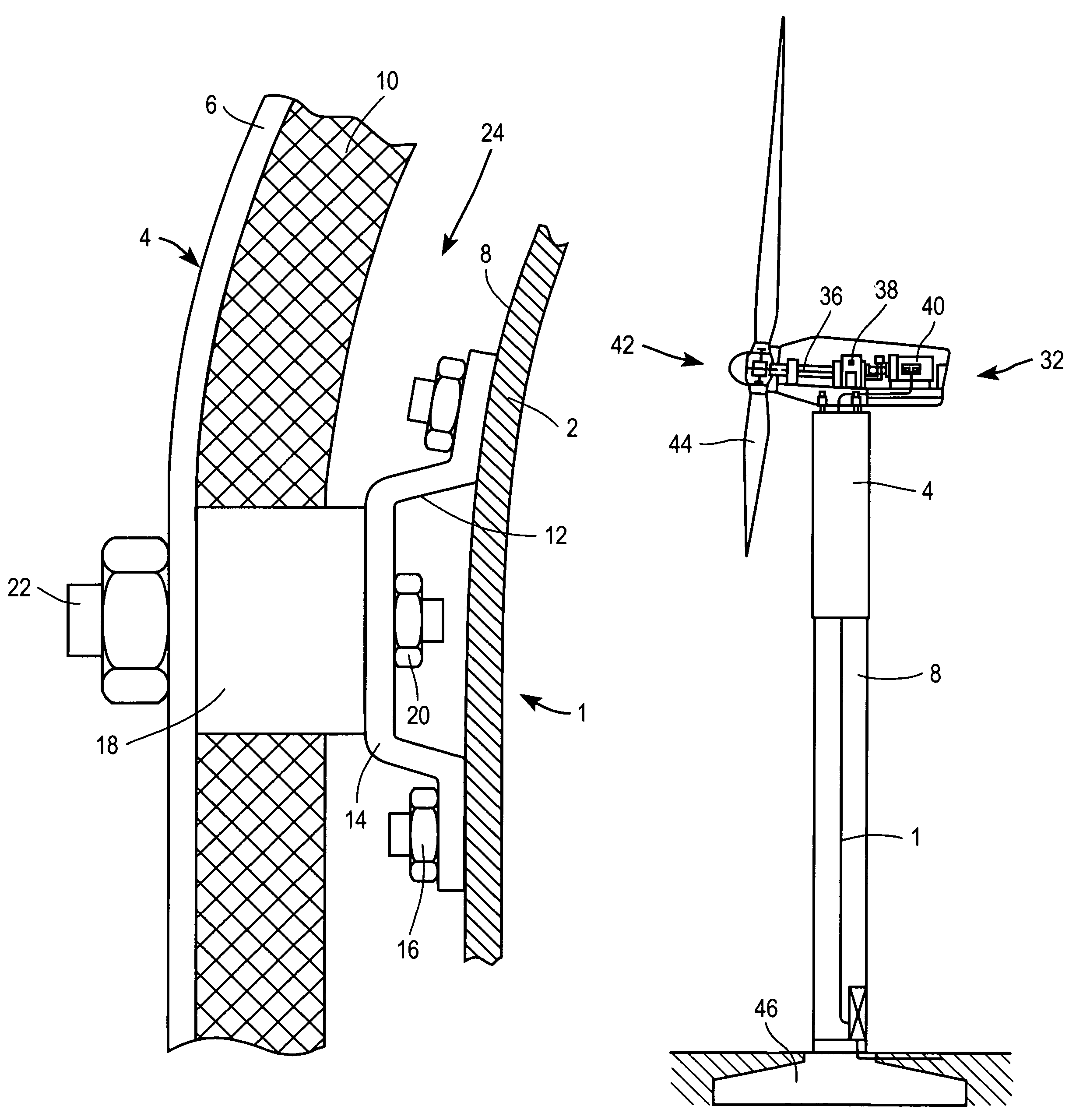
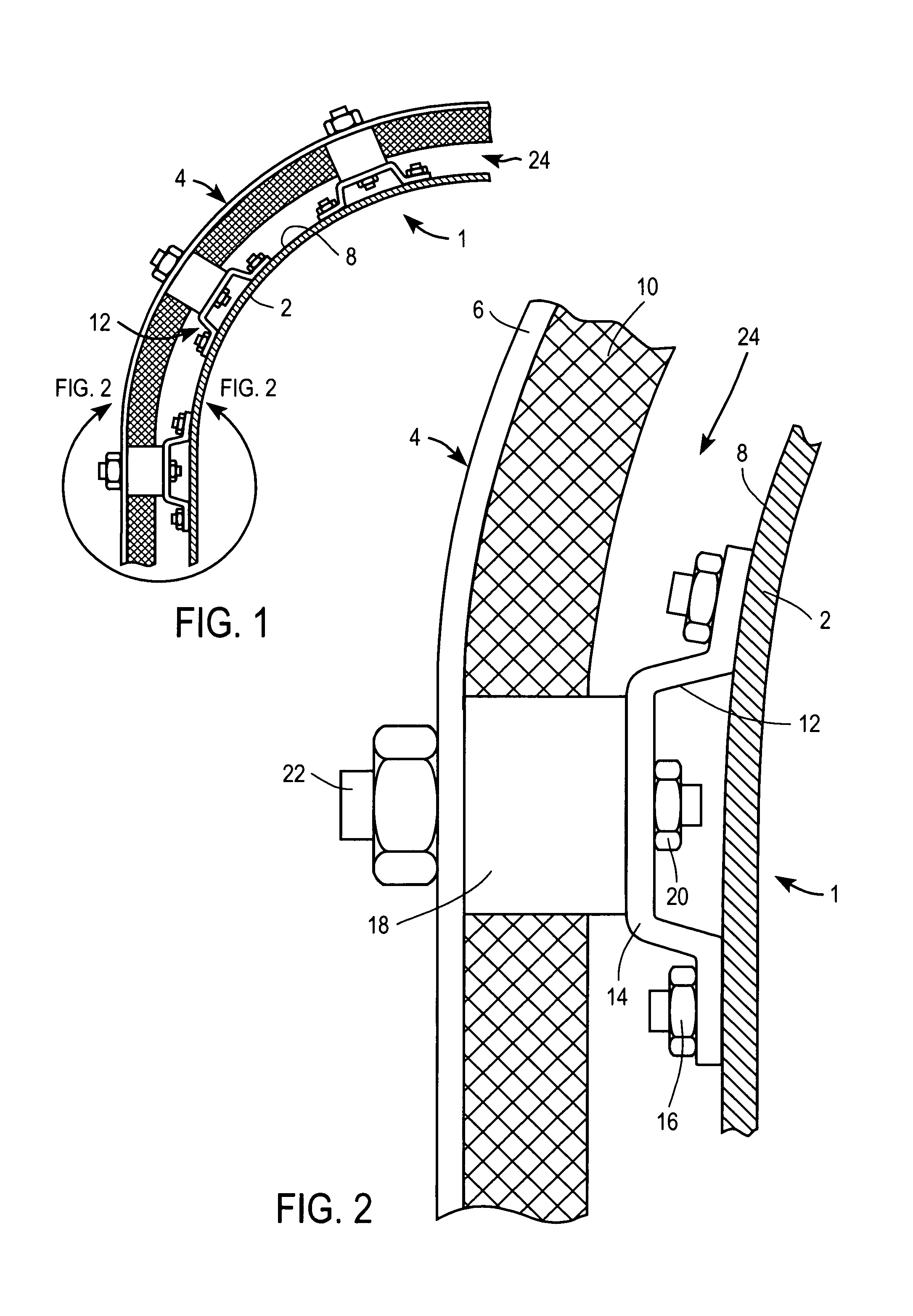
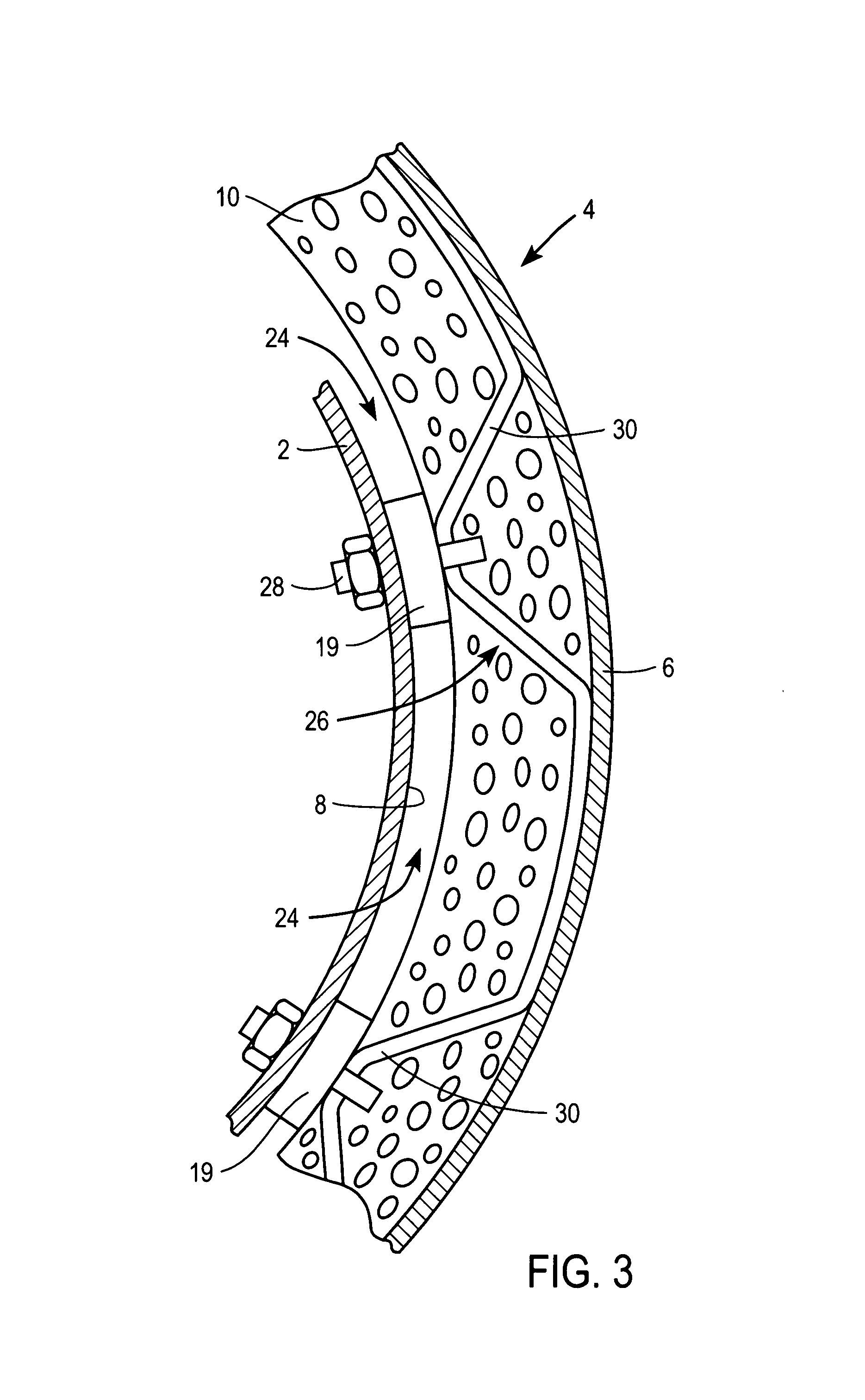
[0024]FIG. 1 shows a part of a tower 1 of a wind turbine. Thereby, the tower wall is denoted as 2 and the noise shell fixed to the outside 8 of the tower wall 2 is denoted as 4. Tower wall 2 and noise shell 4 are separated from each other by air gap 24. The noise shell 4 is fixed to the tower wall 2 only by means of support 12. For better understanding, the sector marked with a circle is drawn to a larger scale in FIG. 2.

[0025]Noise shell 4 is made up of an outer layer 6 and a damping layer 10 directed towards the tower w...


PUM


Abstract

For reduction of the noise radiation of a wind turbine with a tower (1) having an outside (8), a noise shell (4) is provided, which at least partially surrounds the outside (8) of the tower (1) and is positioned at a distance from the outside (8) of the tower (1). An air gap (24) remains between the tower wall (2) and the noise shell (4). The noise emitted from the tower wall (2) is absorbed by the noise shell (4). The noise shell can be composed of a waterproof outer layer (6) and a damping layer (10) directed towards the tower wall (2).

Description

[0001]The present application claims priority to corresponding German Application No. 10341759.1 filed on Sep. 10, 2003, the entire contents of which are hereby incorporated by reference.BACKGROUND OF THE INVENTION[0002]1. Field of the Invention[0003]The invention is in the field of wind turbines and relates to a wind turbine with a tower having an outside.[0004]2. Description of the Related Art[0005]Wind turbines are increasingly used for the generation of electrical energy. Principally, wind turbines consist of a tower, a nacelle located on the tower and a rotor, which is rotatably supported in the nacelle by means of a shaft. In modern wind turbines, the rotor typically has three rotor blades. The rotor blades, which have an aerodynamic profile, experience an ascending force on flowing-against by the wind and, thereby, achieve a rotational movement on the rotor. The shaft of the rotor transmits this rotational movement to a generator accommodated within the nacelle for energy gen...

Claims


Application Information

Patent Timeline
Patent Type & Authority Patents(United States)
IPC IPC(8): F03D11/04B63H1/06F01D5/10F01D5/26F03D1/02F03D9/00F03D11/00G10K11/16
CPCF03D11/00F05B2260/96Y02E10/722Y10S415/909Y10S416/06F03D80/00Y02E10/72
Inventor HESSEL, CHRISTOPH
Owner GENERAL ELECTRIC CO
Why Eureka
Try Eureka