Manufacturing method for magnetic head suspension

a manufacturing method and magnetic head technology, applied in the direction of maintaining the alignment of the head carrier, instruments, photo-taking processes, etc., can solve the problems of reducing the degree of freedom, increasing the number of processes, and affecting the quality of the product, so as to achieve the effect of reducing the cos

Active Publication Date: 2006-12-05
TDK CORPARATION
View PDF10 Cites 41 Cited by
  • Summary
  • Abstract
  • Description
  • Claims
  • Application Information

AI Technical Summary

Benefits of technology

[0008]Accordingly, the present invention is proposed to solve the above-described problem and it is an object of the present invention to provide a manufacturing method for a suspension for a magnetic head in which the thickness of an insulating resin layer can be adjusted without increasing the number of processes and a cost can be reduced.

Problems solved by technology

However, the rigidity of the gimbals part 25 in the vicinity of the slider mounting part 22 conversely becomes too high, so that the degree of freedom is undesirably the more lowered.
However, the above-described related art has such a problem as described below.
That is, two film forming processes of forming the first insulating resin layer 26 and the second insulating resin layer 28 are necessary so that the number of processes is undesirably increased and a cost is inconveniently increased.

Method used


Image

  • Manufacturing method for magnetic head suspension
  • Manufacturing method for magnetic head suspension
  • Manufacturing method for magnetic head suspension

Examples


first embodiment

(First Embodiment)

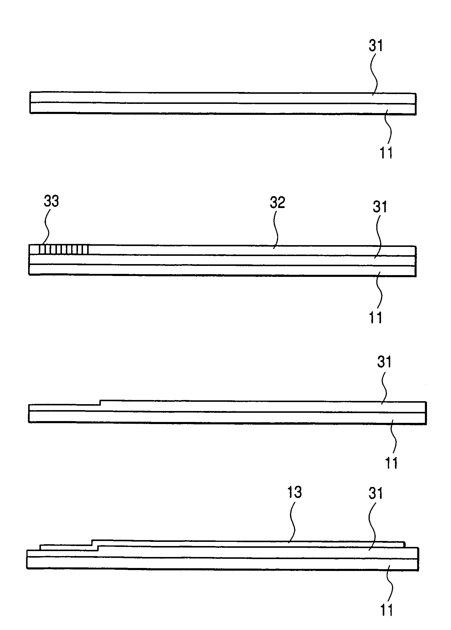
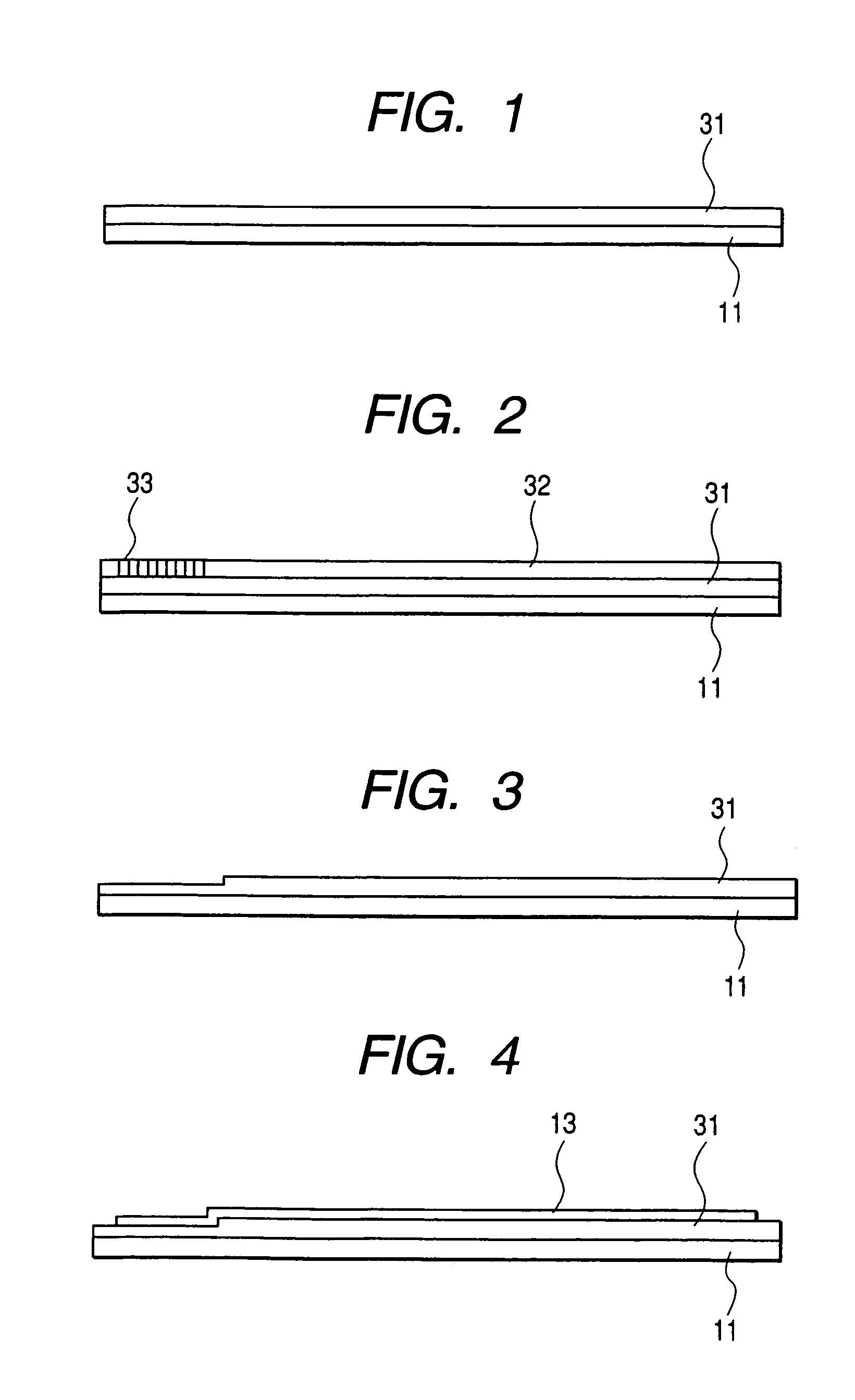
[0030]FIGS. 1 to 5 show a first embodiment. As shown in FIG. 1, an insulating resin layer 31 made of a photo-sensitive resin having a prescribed thickness (for instance, 25 to 30 μm) is formed on a load beam 11. As the photo-sensitive resin, a polyimide resin, an epoxy resin, an acrylic resin, etc. may be preferably used. As a suspension for a magnetic head, a two-piece type in which a flexure serves as a load beam is well-known. In this case, the insulating resin layer 31 is formed on the flexure. Accordingly, in this embodiment, the load beam or the flexure is referred to. However, the load beam is explained below as an example.

[0031]As shown in FIG. 2, a photo-mask 32 is applied to the insulating resin layer 31 and exposed. The photo-mask 32 has a light-proof film made of a chromium film on a transparent base material made of glass. On a part of the light-proof film, slits 33 having a prescribed width (several μm) are formed in parallel at prescribed intervals (...

second embodiment

(Second Embodiment)

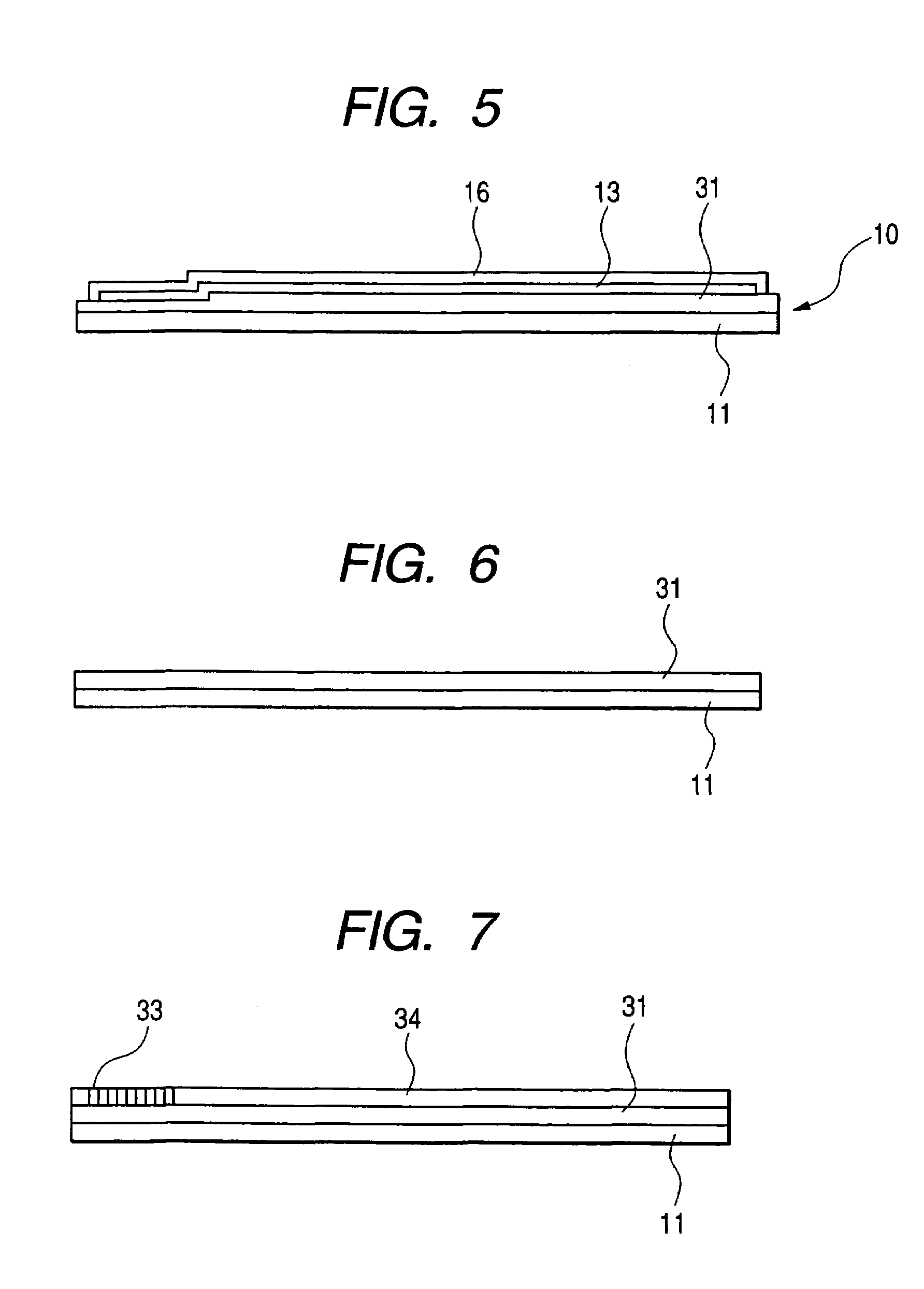
[0040]FIGS. 6 to 8 show a second embodiment of a method for forming the insulating resin layer 31. Firstly, as shown in FIG. 6, a non-photo-sensitive resin is applied to a load beam 11 to form an insulating resin layer 31. Then, as shown in FIG. 7, a photo-sensitive resist is applied to the insulating resin layer 31. The photo-sensitive resist is exposed and developed to form an etching mask 34. On the etching mask 34, slits 33 having a prescribed width (several μm) are partly formed in parallel at prescribed intervals (several μm) to adjust a light transmittance relative to other parts. The part having the slits 33 provided is a part including at least a gimbals part 25 in the vicinity of a slider mounting part 22 in the load beam 11. In parts corresponding to other parts, the resist is left as it is.

[0041]The insulating resin layer 31 is subjected to an etching process by using the etching mask 34 as a mask. As the etching process, any of processing methods such...


PUM

PropertyMeasurementUnit
thicknessaaaaaaaaaa
thicknessaaaaaaaaaa
thicknessaaaaaaaaaa

Abstract

A step of forming an insulating resin layer 31 includes a process of forming the insulating resin layer 31 made of a photo-sensitive resin on a load beam or a flexure 11 and an exposing and developing process in which a photo-mask 32 having different light transmittance between a part corresponding to a part near a slider mounting part 22 and other parts is applied to the insulating resin layer 31, exposed and developed so that the thickness of the insulating resin layer 31 of the part near the slider mounting part 22 is smaller than the thickness of the insulating resin layer 31 of other parts.

Description

BACKGROUND OF THE INVENTION[0001]The present invention relates to a manufacturing method for a suspension for a magnetic head.[0002]As shown in FIG. 9, in the suspension 10 for the magnetic head, a magnetic head element (slider) 12 is mounted on the end side of a load beam 11 made of a spring material such as stainless steel and a wiring pattern 13 electrically connected to the magnetic head element 12 is formed on the load beam 11. The load beam 11 is fixed to an arm part 18 of an actuator 17 through a spacer 14 at one end side thereof to perform a seeking movement (see FIG. 10). FIG. 10 shows a magnetic disk device. Reference numeral 19 designates a spindle and 20 designates a magnetic disk. The wiring pattern 13 is formed on an insulating resin layer 15 made of a polyimide resin, an epoxy resin, an acrylic resin, etc. with a prescribed width on the load beam 11 as shown in FIG. 11. The wiring pattern 13 is further covered with a protective layer 16 made of a photo-sensitive resin...

Claims


Application Information

Patent Timeline
Patent Type & Authority Patents(United States)
IPC IPC(8): G03F7/20G11B21/21G11B5/60B05D5/12G11B5/48
CPCG11B5/4833
Inventor FUJISAKI, HIDEHIKOSATOU, KINNOSUKETAKAHASHI, OSAMU
Owner TDK CORPARATION
Why Eureka
Try Eureka