Eureka AIR delivers breakthrough ideas for toughest innovation challenges, trusted by R&D personnel around the world.

Data tape storage cartridge with removable panel mounted transponder

a technology of data tape and transponder, which is applied in the direction of record information storage, burglar alarm mechanical actuation, instruments, etc., can solve the problems of not being able to rewrite bar code labels, visually readable tags are not well suited to large automated tape libraries, and provide a limited amount of information

Active Publication Date: 2006-12-05
ORACLE INT CORP
View PDF12 Cites 7 Cited by
  • Summary
  • Abstract
  • Description
  • Claims
  • Application Information

AI Technical Summary

Benefits of technology

[0016]According to another aspect of the invention, a tape cartridge for a data storage tape is provided for a tape drive system. The tape drive system has a communication link that reads and writes data to a transponder. The tape cartridge comprises a housing and a tape reel rotatably contained within the housing. A length of data storage tape is ...

Problems solved by technology

Visually readable tags are not well suited for large automated tape libraries.
Bar code labels are not rewriteable and can only provide a limited amount of information.
One disadvantage of radio frequency identification (RFID) tags is that they are normally permanently affixed within the tape cartridge.
A RFID tag that is assembled to the inside of a tape cartridge cannot be easily upgraded.
If the RFID tag is located inside the cartridge, it must be inserted during assembly of the cartridge and cannot be accessed without disassembly of the cartridge.
With this type of RFID tag system, it is not possible to change the write protected data on the RFID chip.
Mounting the RFID chip inside the housing of a tape storage cartridge reduces design flexibility.
In addition, if the RFID tag becomes inoperative for any reason, it is necessary to disassemble the tape cartridge to replace the RFID chip.
If the write protect switch is in the locked position, it is not possible to write to or erase the data storage tape.
If the write protect switch is non-functional or becomes broken in the course of normal use, the cartridge must be disassembled or replaced by another cartridge.
While this design permitted separate assembly and replacement of the write protect switch, it did not disclose or suggest the concept of providing a transponder or RFID tag for the tape storage cartridge.

Method used


Image

  • Data tape storage cartridge with removable panel mounted transponder
  • Data tape storage cartridge with removable panel mounted transponder
  • Data tape storage cartridge with removable panel mounted transponder

Examples


Embodiment Construction

)

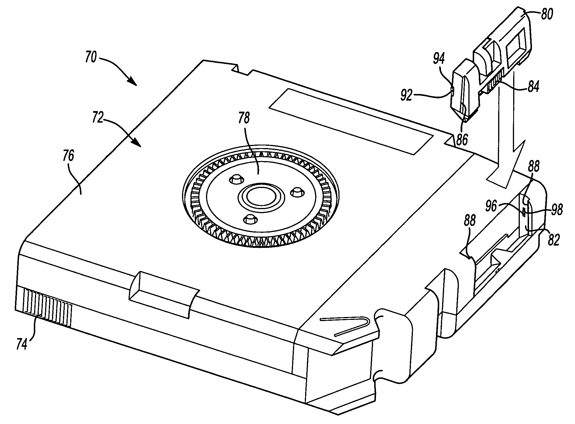
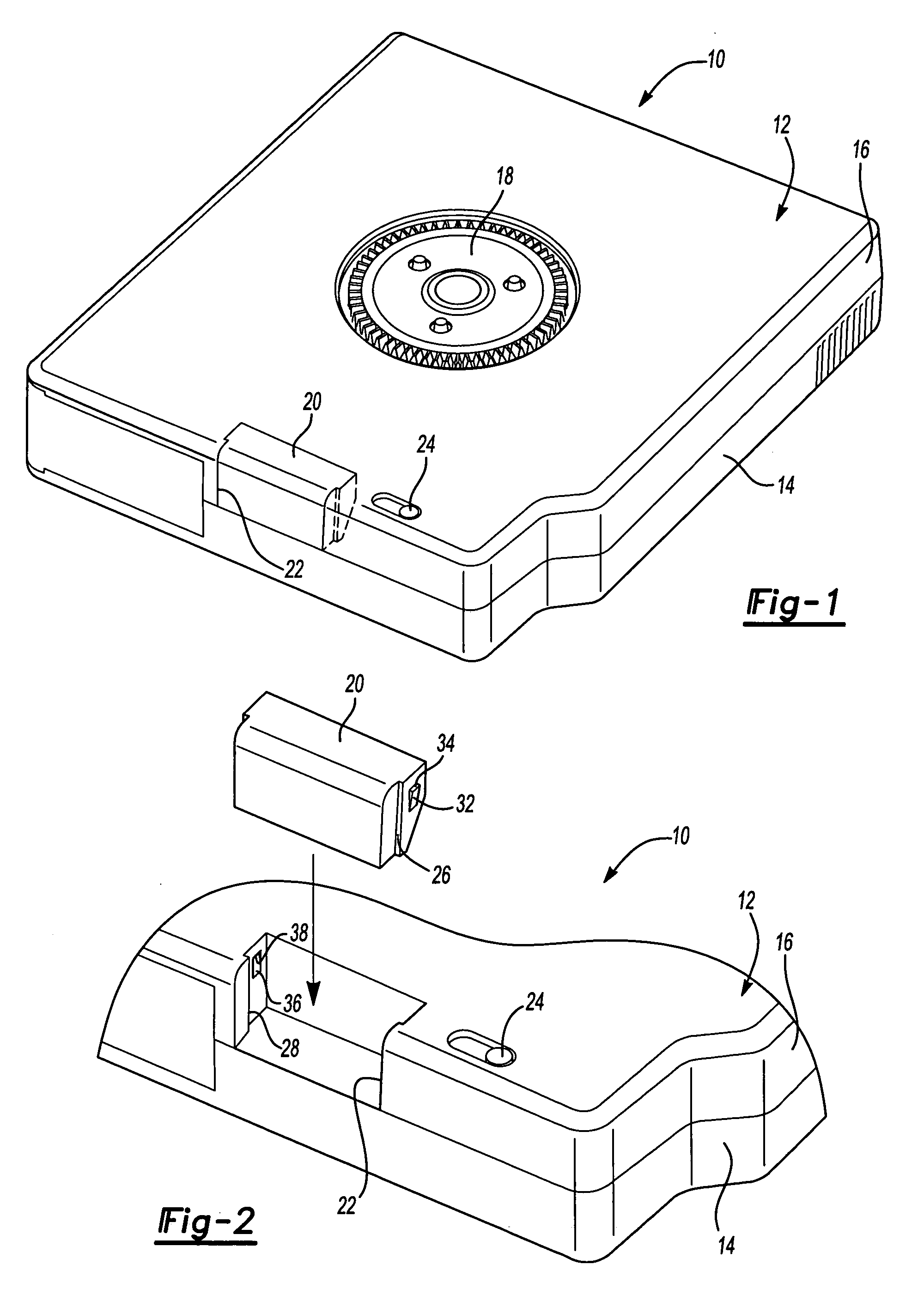
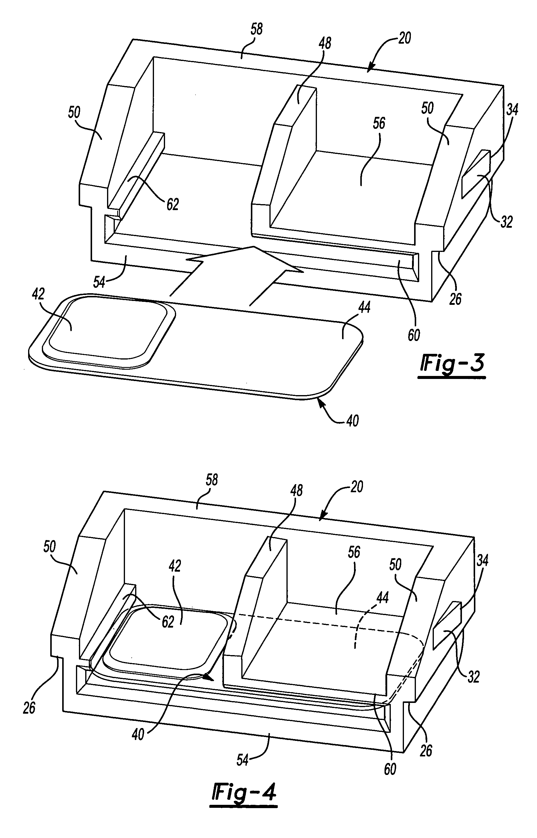
[0026]Referring to FIG. 1, a data storage tape cartridge is generally referred to by reference numeral 10. The data storage tape cartridge comprises a housing 12 having a top portion 14 and a base portion 16. As shown in FIG. 1, the data storage tape cartridge 10 is inverted in a bottom-up orientation to better see the base portion 16. A hub 18 is accessible through the base portion 16. Tape (not shown) is wound around the hub 18 on which data is stored. A removable panel 20 is installed in a window 22 provided in the base portion 16 of the housing 12. It should be understood that the removable panel 20 and window 22 could be provided in the top portion 14 or partially within the top portion 14 and base portion 16. A write protect switch 24 may also be provided on the housing 12 in the base portion 16, as shown. The write protect switch 24 may be moved between a first position in which data may not be written to the tape, and a second position in which data may be written to the ta...


PUM


Abstract

A data tape storage cartridge for a data storage system that has a transponder for reading and writing data. The data storage tape cartridge includes a housing having a window and at least one wall. A panel is retained on the housing and configured to cover the window. A retainer is provided on the panel for the transponder. The transponder functions as an identification tag to which data is written and from which data is read to identify the data storage tape cartridge. The removable panel may also include a write protect switch that may be actuated to prevent a tape from being overwritten.

Description

CROSS-REFERENCE TO RELATED APPLICATIONS[0001]This application is a continuation-in-part of U.S. application Ser. No. 10 / 746,064 filed Dec. 26, 2003.BACKGROUND OF THE INVENTION[0002]1. Field of the Invention[0003]The present invention relates to a data storage tape cartridge having a housing within which a transponder is secured for identification of the cartridge.[0004]2. Background Art[0005]Tape cartridges provide a practical and economical mechanism for long-term data storage. Tape cartridges have one or two reels on which a data storage tape is wound. Data storage tapes are comprised of a flexible web on which a coating is applied that records information caused by changes in magnetic fields, exposure to light, and the like. A data storage tape cartridge is inserted into a tape drive to allow data to be written to, or read from, the data tape.[0006]Single hub cartridges are accessed by a tape drive as the tape is withdrawn from the cartridge and pulled along a tape path across at...

Claims


Application Information

Patent Timeline
IPC IPC(8): G08B13/14
CPCG08B13/2417G08B13/242G11B23/042G11B23/107
Inventor WOJCIECHOWSKI, MATTHEW P.VENO, WILLIAM T.
Owner ORACLE INT CORP
Why Eureka
Eureka Blog
Learn More