Fiber optic cable and plug assembly

a fiber optic cable and plug technology, applied in the direction of fibre mechanical structure, instruments, optical light guides, etc., can solve the problem of unresolved need for fiber optic cables

Active Publication Date: 2006-12-05
CORNING OPTICAL COMM LLC
View PDF24 Cites 126 Cited by
  • Summary
  • Abstract
  • Description
  • Claims
  • Application Information

AI Technical Summary

Benefits of technology

[0007]To achieve the foregoing and other objects, and in accordance with the purposes of the invention as embodied and broadly described herein, the present invention provides various embodiments of a fiber optic cable and plug assembly, and more particularly, a fiber optic cable having a plug assembly that may be positioned and secured at any desired location along the length of the cable. Thus, the present invention provides a fiber optic cable, referred to herein as a secondary distribution cable, whose length may be readily adjusted either in the factory or the field so that the cable may be used regardless of the distance between interconnection points. The present invention further provides a length of fiber optic cable and a plug assembly adapted to engage a receptacle of a connector port provided in an external wall or an internal wall of a network connection terminal.
[0008]In an exemplary embodiment, the present invention provides a plug assembly for a fiber optic cable, wherein a portion of the fiber optic cable continues beyond the plug assembly when the plug assembly engages a receptacle of a connector port provided in an external wall or an internal wall of a network connection terminal. The plug assembly is adapted to be positioned and secured at any desired location along the length of the cable, and thus, includes a plug shroud secured at the desired location along the length of the fiber optic cable. A forward portion of the plug shroud has one or more extensions at one end for mating with a receptacle disposed within a connector port provided in an external wall or an internal wall of the connection terminal. In one embodiment, at least two extensions of the plug shroud have different profiles for keying the plug assembly with the receptacle. The plug assembly further includes a coupling nut operable for securing the plug assembly to the receptacle, a heat shrink tube disposed about a rearward portion of the plug shroud and the cable jacket for sealing the fiber optic cable, and a boot for providing bending strain relief to the fiber optic cable near the plug assembly. In a further embodiment, the plug assembly includes a crimp body made up of two mating halves defining a clamping portion for securing a strength component of the fiber optic cable, and a crimp band for securely holding the two halves of the crimp body together. The plug shroud may be secured to the fiber optic cable using the crimp body and the crimp band. Alternatively, the crimp body and the crimp band may be eliminated and the plug shroud secured to the fiber optic cable using an adhesive material, such as epoxy resin or potting compound.
[0010]In yet another embodiment, the present invention provides a fiber optic cable assembly including a fiber optic cable having a cable jacket and an optical transmission component disposed within the cable jacket, and a plug assembly adapted to be positioned and secured at any desired location along the length of the fiber optic cable. The plug assembly includes a plug shroud secured at the desired location and the plug shroud has means for mating the plug assembly with a receptacle disposed within a connector port provided in an external wall or an internal wall of a network connection terminal. The plug assembly further includes a coupling nut operable for securing the plug assembly to the receptacle, a heat shrink tube disposed about a rearward portion of the plug shroud and the cable jacket for sealing the fiber optic cable, and a boot for providing bending strain relief to the fiber optic cable near the plug assembly. In a further embodiment, the plug assembly includes a crimp body made up of two mating halves defining a clamping portion for securing a strength component of the fiber optic cable, and a crimp band for securely holding the two halves of the crimp body together. The plug shroud may be secured to the fiber optic cable using the crimp body and the crimp band. Alternatively, the crimp body and the crimp band may be eliminated and the plug shroud may be secured to the fiber optic cable using an adhesive material, such as epoxy resin or potting compound.

Problems solved by technology

As yet however, there is an unresolved need for a fiber optic cable and plug assembly adapted to utilize a connector port provided in an external wall or an internal wall of a connection terminal to route more than one optical fiber of the distribution cable to a remote location.

Method used


Image

  • Fiber optic cable and plug assembly
  • Fiber optic cable and plug assembly
  • Fiber optic cable and plug assembly

Examples


Embodiment Construction

[0022]The present invention will now be described more fully hereinafter with reference to the accompanying drawings in which exemplary embodiments of the invention are shown. However, this invention may be embodied in many different forms and should not be construed as limited to the embodiments set forth herein. These exemplary embodiments are provided so that this disclosure will be both thorough and complete, and will fully convey the scope of the invention to those skilled in the art. Like reference numbers refer to like elements throughout the various drawings.

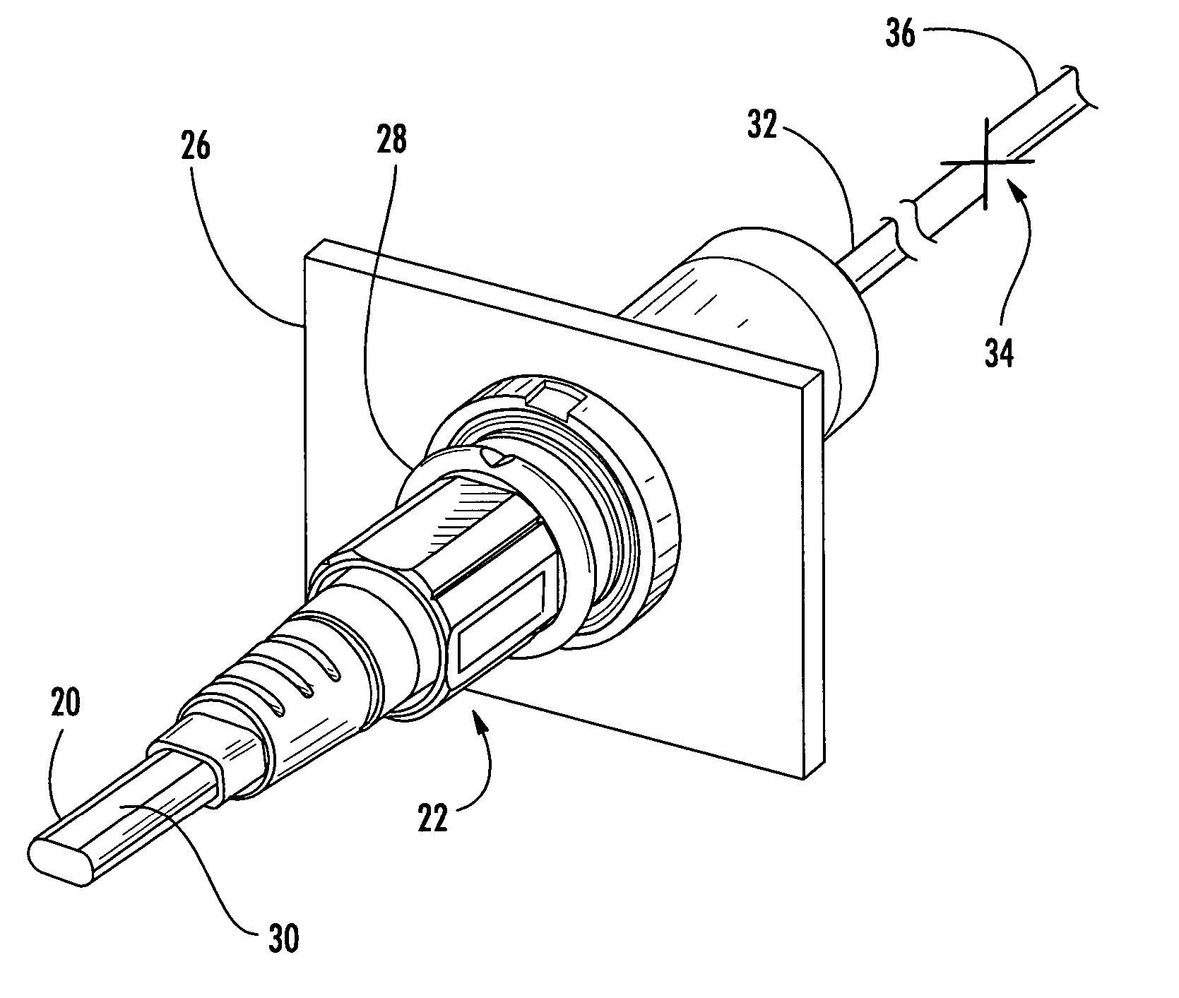
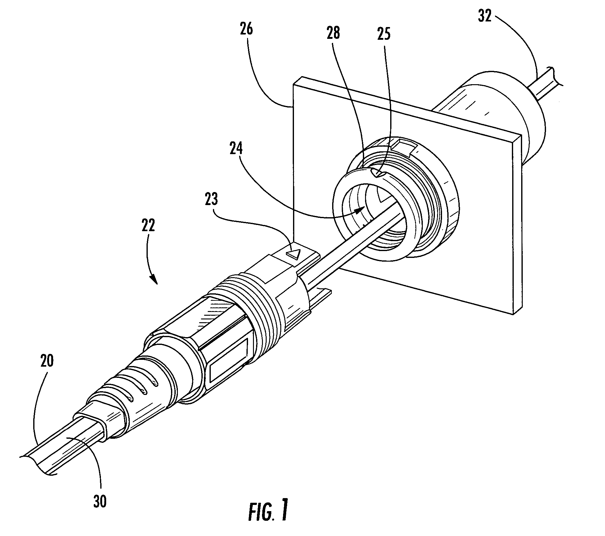
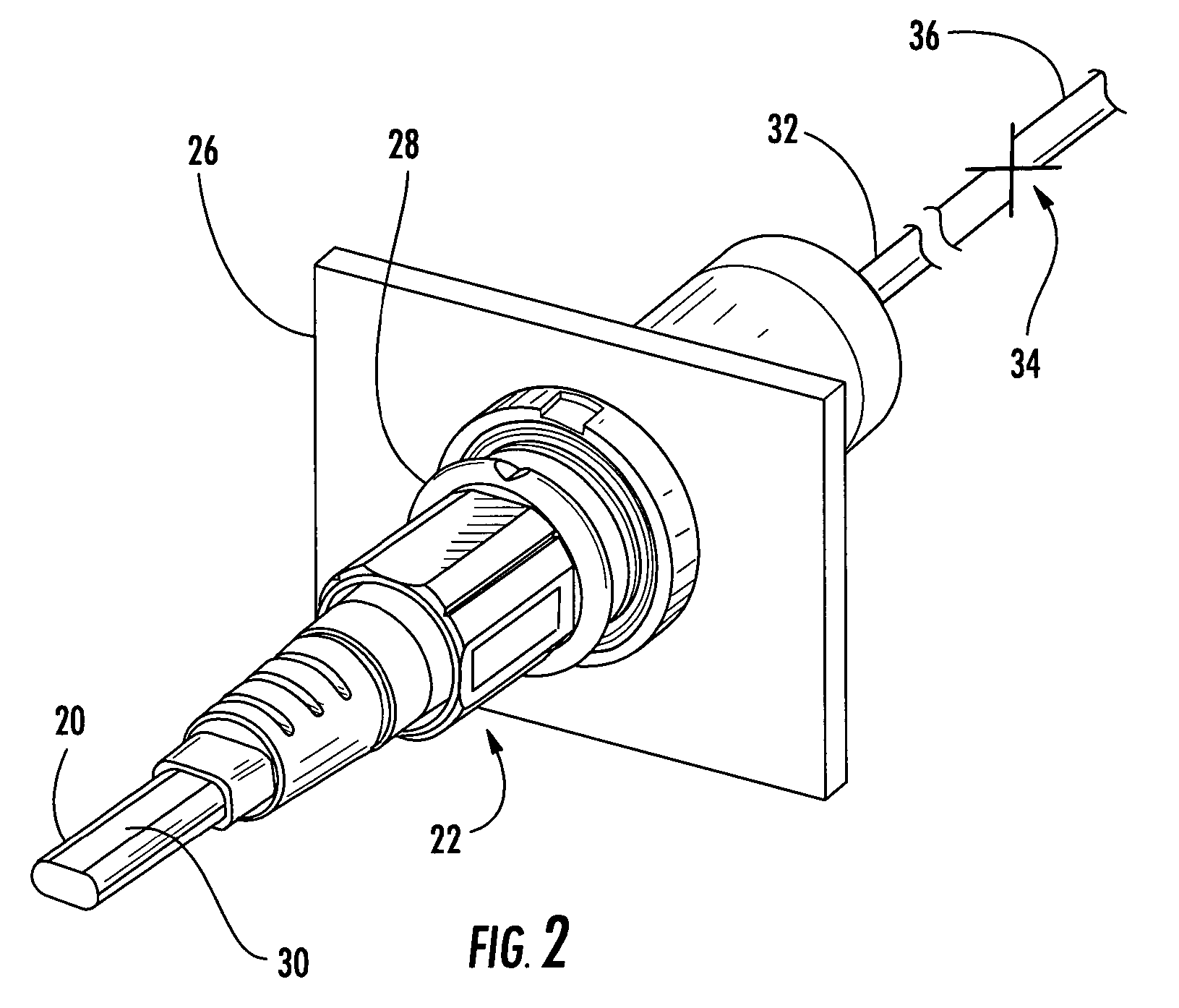
[0023]In the various embodiments described below, the present invention comprises a fiber optic cable having a plug assembly that may be positioned and secured at any desired location along the length of the cable, thus providing a fiber optic cable whose length may be readily adjusted either in the factory or in the field so that it may be used to establish an optical connection regardless of the distance between interc...


PUM


Abstract

A fiber optic cable has a plug assembly that may be positioned and secured at any desired location along the length of the cable to engage a receptacle disposed within a connector port provided in a wall of a connection terminal. The plug assembly includes a shroud, a coupling nut, a heat shrink tube for sealing the cable and a boot for providing bending strain relief. At least a portion of the cable passes through the connector port for interconnection with optical fibers of a distribution cable or optical equipment. A method for routing a fiber optic cable into a connection terminal includes using a connector port provided in a wall of the terminal, determining a desired length of the cable, positioning and securing a plug assembly at a desired location along the length of the cable, and mating the plug assembly with a receptacle disposed within the connector port.

Description

BACKGROUND OF THE INVENTION[0001]1. Field of the Invention[0002]The present invention relates generally to a fiber optic cable and plug assembly for a fiber optic communications network, and more specifically, to a secondary distribution cable having a plug assembly that may be positioned and secured at any desired location along the length of the cable.[0003]2. Description of the Related Art[0004]Optical fiber is increasingly being used for a variety of broadband applications including voice, video and data transmissions. As a result of the ever-increasing demand for broadband communications, fiber optic networks are being expanded to provide services to an end user, commonly referred to as a subscriber. In this regard, fiber optic networks are being developed that deliver “fiber-to-the-curb” (FTTC), “fiber-to-the-business” (FTTB), “fiber-to-the-home” (FTTH), and “fiber-to-the-premises” (FTTP), referred to generically as “FTTx.”[0005]In order to reduce installation labor costs in F...

Claims


Application Information

Patent Timeline
Patent Type & Authority Patents(United States)
IPC IPC(8): G02B6/00G02B6/36G02B6/38G02B6/42G02B6/44
CPCG02B6/387G02B6/3887G02B6/4471G02B6/3829G02B6/3889G02B6/389G02B6/3897G02B6/4452G02B6/3888G02B6/3875G02B6/4478
Inventor VO, CHANH C.CASTONGUAY, GUYTRAN, HIEU V.
Owner CORNING OPTICAL COMM LLC
Why Eureka
Try Eureka