Actuating device for doors or hatches of vehicles

a technology for actuating devices and doors, applied in the direction of mechanical control devices, keyhole guards, instruments, etc., can solve the problems of making the manoeuvre of unauthorized persons designed to remove the turret from the inventive device more difficult, and achieve the effect of greater resistance to being pulled

Active Publication Date: 2006-12-12
HUF HULSBECK & FURST GMBH & CO KG
View PDF11 Cites 21 Cited by
  • Summary
  • Abstract
  • Description
  • Claims
  • Application Information

AI Technical Summary

Benefits of technology

[0008]The invention is based on the task of developing an actuating device of the type indicated above which includes a turret with greater resistance to being pulled out of the carrier and which prevents unauthorized persons from performing manipulations which could allow removal of the turret.
[0009]In accordance with the invention, the rocker arm pivotably supported in the carrier has several functions. According to the first function, the control curve provided on the rocker arm moves a slide, which is guided with freedom of movement on the carrier, out of a locking position, in which at least one blocking surface on the slide is engaged with an opposing blocking surface on the turret, into a release position, in which the blocking surface on the slide releases the opposing surface on the turret. According to the second function, the thrust surface provided on the rocker arm shifts the turret back in the carrier to such an extent that the shoulder on the turret releases the opposing shoulder on the carrier, this movement thus constituting a reversal of the shift phase of the original setting movement. It is now possible, of course, to pull the turret easily out of the carrier in a manner which represents a reversal of the plug-in phase of the setting movement originally performed during the installation procedure. The rocker arm performs its third function during the installation of the turret. During the plug-in phase, the turret comes in contact with the thrust surface and thus pivots the rocker arm out of its starting position and toward its end position. The rocker arm then in fact reaches this end position upon completion of the parallel shift phase of the turret in the carrier. Because of the functions performed by the rocker arm, the turret can be installed in the carrier very easily and quickly, and it can be removed from the actuating device again with equal ease and speed. In the device according to the invention, the turret has surprisingly strong resistance to being pulled out of the carrier.
[0010]When the actuating end of the rocker arm is positioned on the rear surface of the carrier, opposite the handle, manipulations by unauthorized persons designed to remove the turret from the inventive device are made more difficult. The rocker arm is located on the inside of the door and is therefore virtually inaccessible to unauthorized persons. Only after the door has been opened are the openings accessible, through which a tool such as a screwdriver could be inserted to pivot the rocker arm. Only an authorized person, i.e., a person who has a key which fits the lock cylinder in the turret, can open the door. The inventive device makes a vehicle thus equipped theft-proof; unauthorized persons are prevented from gaining access to the interior of the vehicle.

Problems solved by technology

When the actuating end of the rocker arm is positioned on the rear surface of the carrier, opposite the handle, manipulations by unauthorized persons designed to remove the turret from the inventive device are made more difficult.

Method used


Image

  • Actuating device for doors or hatches of vehicles
  • Actuating device for doors or hatches of vehicles
  • Actuating device for doors or hatches of vehicles

Examples


Embodiment Construction

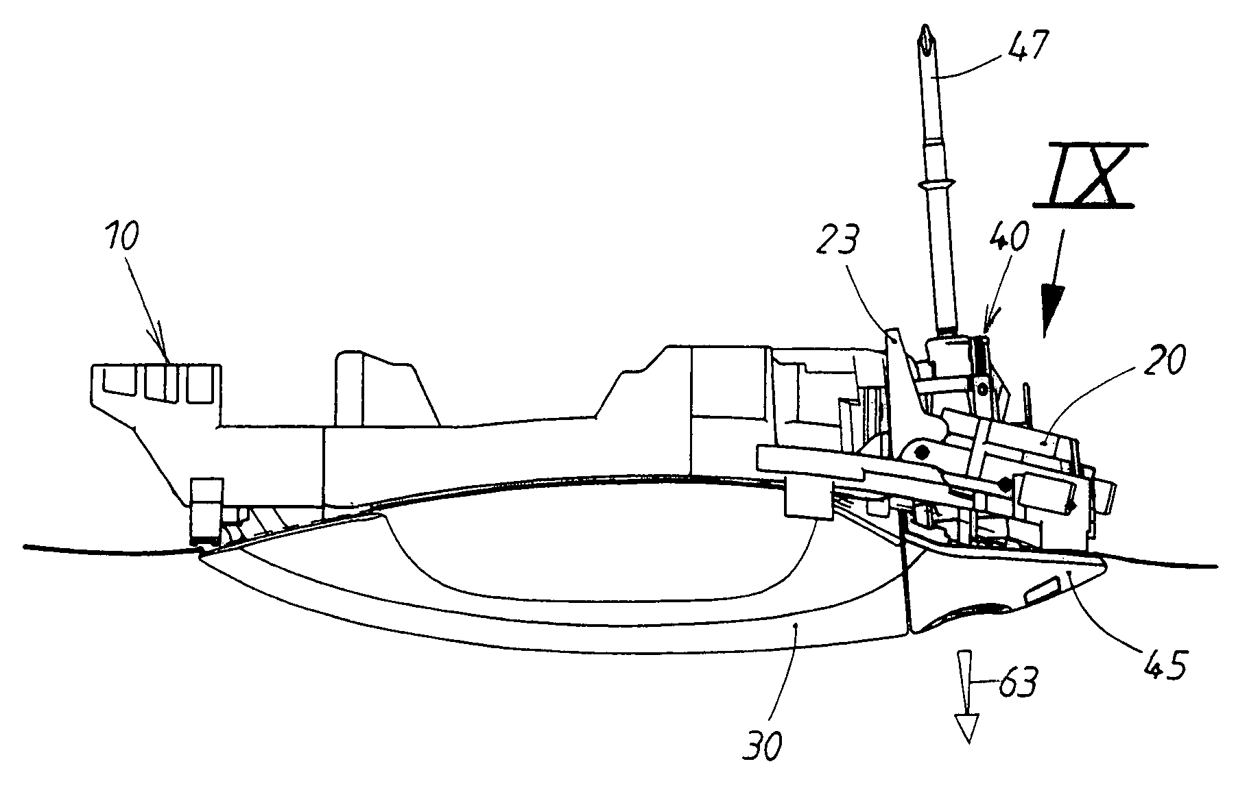
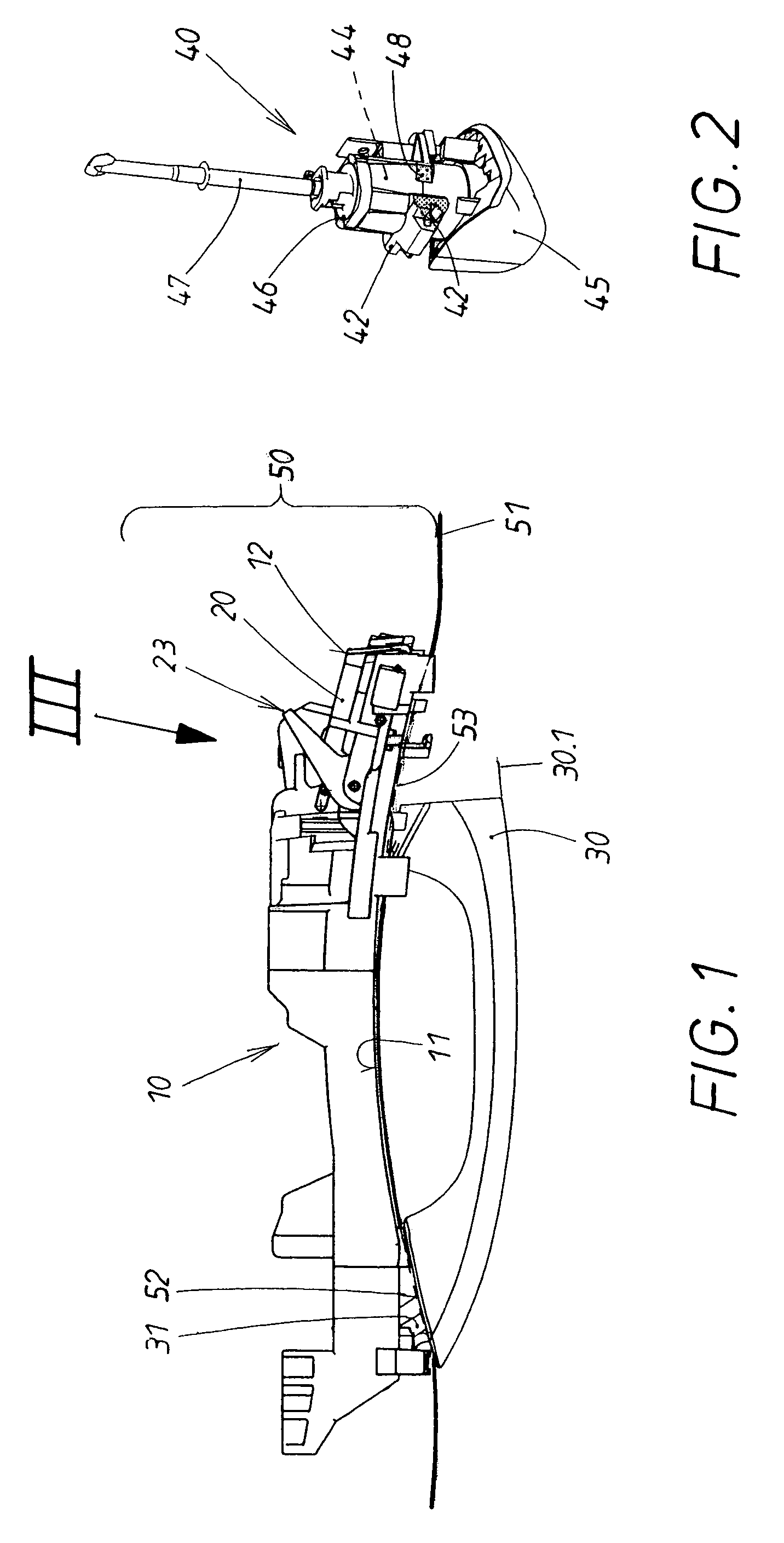
[0026]As can be seen from FIGS. 1 and 2, the actuating device consists of a carrier 10 with a slide 20, connected to it to form a single component; a handle 30; and a turret 40. The carrier 10 is attached to the interior of the door 50 from the inside surface of the door, which is not shown in detail. The slide 20 is guided with freedom of longitudinal movement on the rear surface 12 of the end section of the carrier 10, as will be described later in more detail. The exterior panel 51 of the door 50 rests against the front surface 11 of the carrier. So that the handle 30 and the turret 40 can be installed, the exterior panel 51 of the door is provided with two openings 52, 53.

[0027]The handle 30 is introduced from the outside surface of the door 50 through the openings 52, 53 into the carrier 10. For this purpose, the handle has at one end a bearing end 31, which is passed through the one opening 52 and hooked onto a bearing block in the carrier 10 (not shown). In this exemplary emb...


PUM


Abstract

In an actuating device, the turret is installed in a carrier and removed from it by a setting movement. The setting movement comprises a plug-in phase and a shift phase during the installation procedure. Thus a shoulder on the turret arrives behind an opposing shoulder on the carrier. A locking screw secures the installed turret on the carrier. A rocker arm is supported pivotably on the carrier, which rocker arm has a control curve and a thrust surface and which can be pivoted between a starting position and an end position. In addition, the carrier is provided with a slide, which can also be shifted between a release position and locking position. Upon moving into the locking position, blocking surfaces on the slide arrive behind the opposing blocking surface on the turret. During the installation of the turret, the turret pushes against the thrust surface of the rocker arm and pivots the rocker arm toward its end position. During the removal of the turret, the thrust surface of the rocker arm ensures that the turret is pushed back in the carrier until the shoulder and the opposing shoulder release each other.

Description

BACKGROUND OF THE INVENTION[0001]1. Field of the Invention[0002]The present invention relates to an actuating device.[0003]2. Description of the Related Art[0004]A so-called “turret” can hold either a real lock cylinder or a dummy cylinder for the sake of styling. A turret of this type is usually mounted in the carrier and removed from it again from the outside of the door only after the carrier has been attached to the inside of the door. This is done by a setting movement of the carrier, which consists of two different, successive components. The first phase of the setting movement required to install the turret is a “plug-in” phase, during which the turret is inserted into an opening in the carrier. This is followed by a “shift phase”, in which the inserted turret is subjected to a parallel shift in the carrier. During this parallel shift in the opening in the carrier, at least one lateral shoulder on the turret arrives behind an opposing shoulder on the carrier. A locking screw ...

Claims


Application Information

Patent Timeline
Patent Type & Authority Patents(United States)
IPC IPC(8): E05B13/10E05B65/20
CPCE05B79/06E05B85/16Y10S292/31Y10T70/5761Y10T70/5889Y10T70/7655Y10T70/8541Y10T292/57
Inventor MATHOFER, REINHOLD
Owner HUF HULSBECK & FURST GMBH & CO KG
Why Eureka
Try Eureka