Cable management apparatus

a management apparatus and cable technology, applied in the field of firefighting equipment, can solve the problems of increasing the cost and complexity of the monitor, the manual operation of the handwheel, and the need for individual slip rings, so as to achieve the effect of maintaining the integrity of the electrical connection and being easy to assembled

Active Publication Date: 2006-12-12
TASK FORCE TIPS
View PDF19 Cites 15 Cited by
  • Summary
  • Abstract
  • Description
  • Claims
  • Application Information

AI Technical Summary

Benefits of technology

[0011]The wiring skirt preferably further comprises at least two clamps, one each for fixing the intermediate section of the wire to a corresponding one of the first portion and the second portion of the wiring skirt. The clamps are positioned on the outside of the wiring skirt immediately adjacent each of the first and second openings. The clamps fix the cable to the two wiring skirt portions so that the cable does not slip within the wiring channel in the skirt. In one feature of the invention, the clamps also help maintain the portion of the cable immediately adjacent the openings at a generally parallel orientation with respect to the upper and lower extents of the wiring channel.
[0014]The wiring or cable is introduced into or exits the wiring skirt through the openings in first and second skirt portions. In one aspect, the outer and annular walls of the two portions define indentations into the corresponding circumferential channels. These indentations facilitate introduction of the cable into the wiring skirt generally parallel to the base of the wiring channels, which helps prevent crimping or buckling of the cable and its bend portion.
[0017]The cable management apparatus further includes a cable containing the at least one wire, the cable entering the circumferential channel through the first opening and exiting the circumferential channel through the second opening. In one aspect of the invention, the cable defines a 180° bend between an upper portion and a lower portion of the cable, whereby the upper portion overlaps the lower portion within the circumferential channel. This bend essentially travels around the circumferential channel as the second or upper skirt portion rotates relative to the stationary first skirt portion. As the bend moves around the circumferential channel, the upper and lower portions of the cable coil and un-coil about the lower and upper skirt portions. In one embodiment, this feature of the invention allows the rotating element to rotate through a sweep of 4500 relative to the stationary element of the monitor, while the cable management apparatus keeps the electrical wiring protected and contained.
[0019]It is one object to provide a wire or cable management apparatus for use with a fire fighting monitor that can accommodate a wide angular sweep of the rotating element of the monitor. A further object is achieved by aspects of the invention that protect the electrical wiring from water that may surround the fire fighting monitor.
[0020]One benefit of the cable management apparatus of the present invention is that it can be easily assembled on an existing fire fighting monitor or water cannon. A further benefit is that the invention maintains the integrity of the electrical connection between electrical components on the rotating element of the monitor and a remote electrical source. Other benefits and objects of the invention will become apparent upon consideration of the following written description and accompanying figures.

Problems solved by technology

This remote control is necessary where manual operation of handwheels is problematic.
One problem posed by the slip ring system is that individual slip ring arrangements are required for each electrical connection.
However, wireless transmission requires that rotating body of the monitor carry a receiver, which increases the cost and complexity of the monitor.
The wireless approach thus requires a transmitter on the monitor, which again increases the cost and complexity of the system.
One significant drawback of the slip ring system is that the metallic conductors are prone to corrosion.
This problem is exacerbated because the monitor is by its very nature used in a wet environment.
Water within the slip rings not only speeds up corrosion, it also disrupts the electrical contact between the slip ring components.

Method used


Image

  • Cable management apparatus
  • Cable management apparatus
  • Cable management apparatus

Examples


Embodiment Construction

[0032]For the purposes of promoting an understanding of the principles of the invention, reference will now be made to the embodiments illustrated in the drawings and described in the following written specification. It is understood that no limitation to the scope of the invention is thereby intended. It is further understood that the present invention includes any alterations and modifications to the illustrated embodiments and includes further applications of the principles of the invention as would normally occur to one skilled in the art to which this invention pertains.

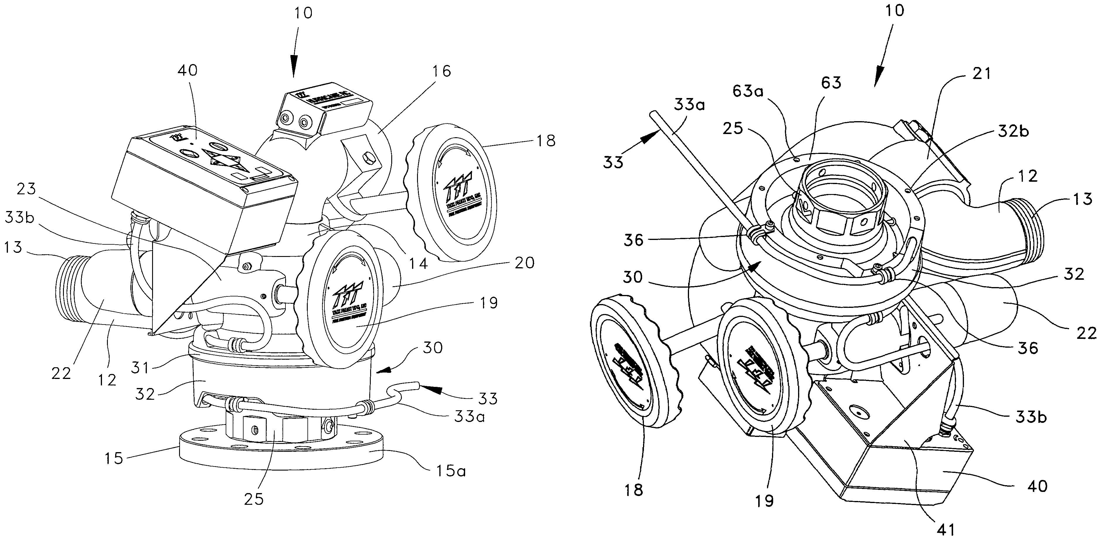
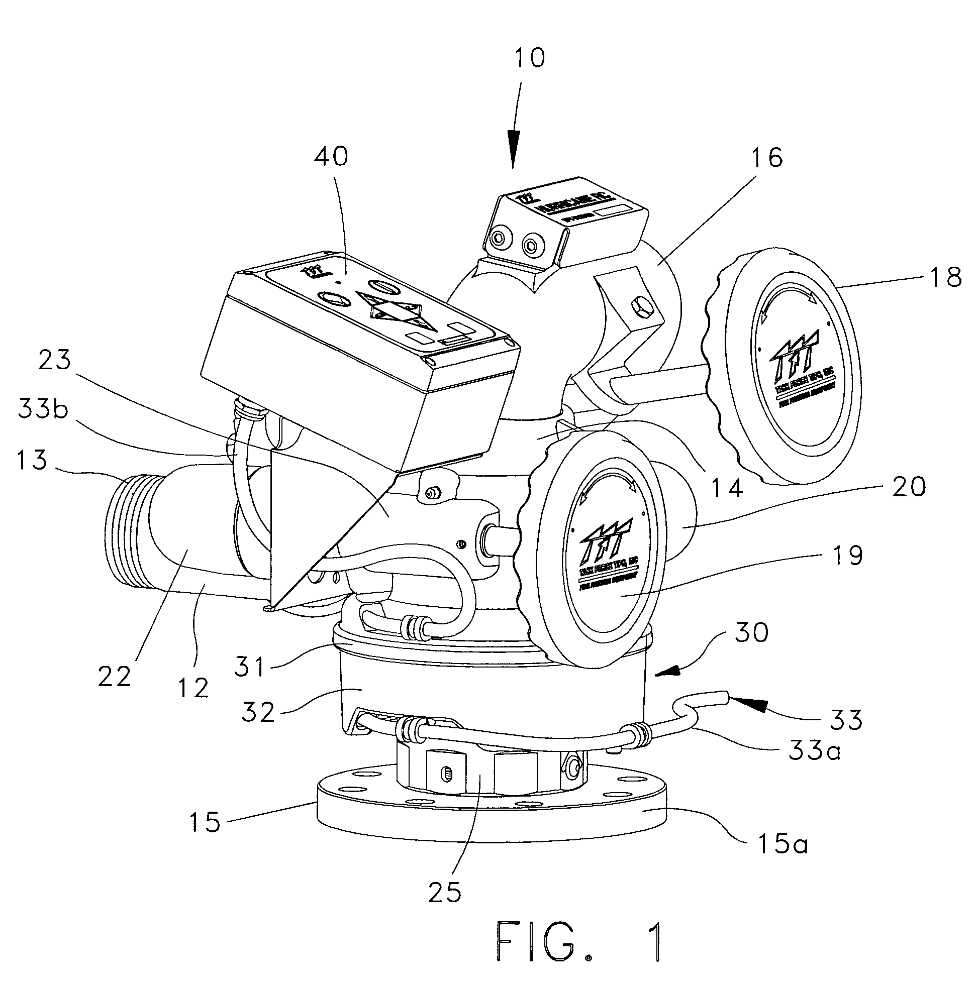
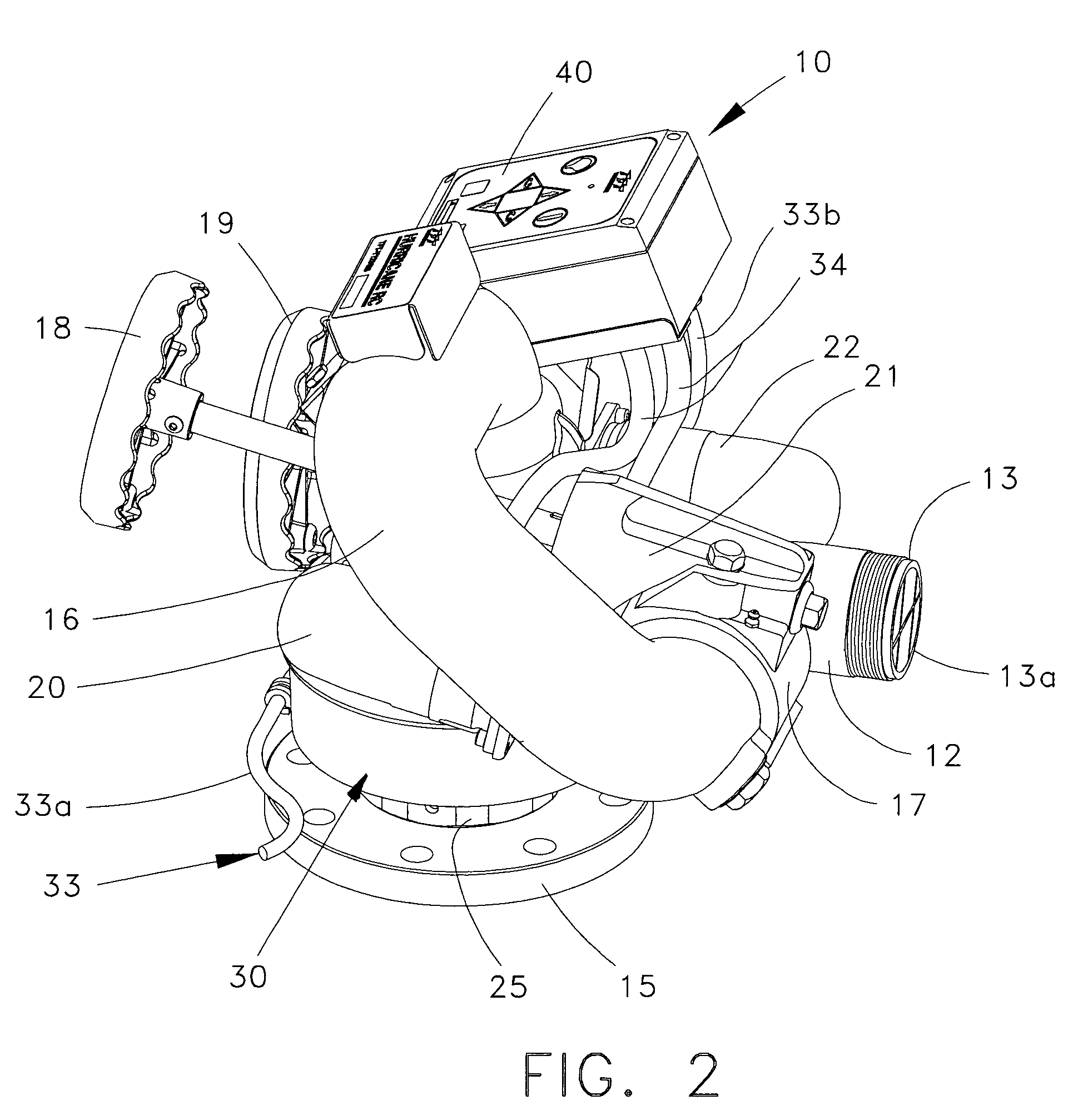
[0033]The present invention contemplates a wiring cable management apparatus for use with a fire fighting monitor or water cannon, such as the water monitor 10 depicted in FIGS. 1–5. The monitor 10 can be of a variety of configurations capable of at least rotational adjustment in a horizontal plane (i.e., rotation about a vertical axis). For the purposes of the present disclosure, the water monitor 10 depicted i...


PUM


Abstract

A fire fighting monitor includes a stationary element and a rotating element for directing a water stream at variable trajectories. Electrical components, such as drive motors, are mounted on the rotating element and are connected to electrical sources remote from the monitor. A wire management system is provided for the monitor that protects the electrical wiring while accommodating relative rotation between the stationary and rotating elements of the monitor. In one embodiment, the wire management system includes a two-piece wiring skirt with a first portion connected to the stationary element and a second portion connected to the rotating element. The two portions define a circumferential channel and associated openings for passage of a wiring cable. The cable incorporates a 180° bend within the channel that travels around the channel as the cable coils and un-coils within the channels of the two portions.

Description

BACKGROUND OF THE INVENTION[0001]The present invention relates to fire-fighting equipment, and more particularly to a monitor or water cannon that can be aimed in any direction and at any elevational angle. The invention specifically relates to a system for accommodating wiring to electrical components mounted on the rotating monitor.[0002]In fire fighting, water cannons or monitors are used to direct a stream of water onto a specific location. Monitors can be mounted on a fire truck or on an aerial ladder assembly—anywhere that allows the monitor to accurately direct the water stream. The typical modern monitor permits adjustment of the elevational angle of the monitor nozzle to vary the distance over which the stream is directed. In addition, the monitor can be rotated in a horizontal plane so that the water stream can be precisely positioned regardless of the location and orientation of the fire truck of aerial ladder.[0003]In many water cannons or monitors, the elevational and r...

Claims


Application Information

Patent Timeline
Patent Type & Authority Patents(United States)
IPC IPC(8): A62C2/00A62C25/00
CPCH02G11/003A62C31/24
Inventor KOLACZ, DAVID J.STEINGASS, ROBERT W.
Owner TASK FORCE TIPS
Why Eureka
Try Eureka