
Elevator control using switched speed and position

a technology of switching speed and position, applied in the direction of computer control, instruments, electrical apparatus, etc., can solve the problems of difficult speed reference, difficult application, and complicated publication, and achieve the effect of simple implementation

Active Publication Date: 2006-12-12
KONE CORP
View PDF11 Cites 8 Cited by
  • Summary
  • Abstract
  • Description
  • Claims
  • Application Information

AI Technical Summary

Benefits of technology

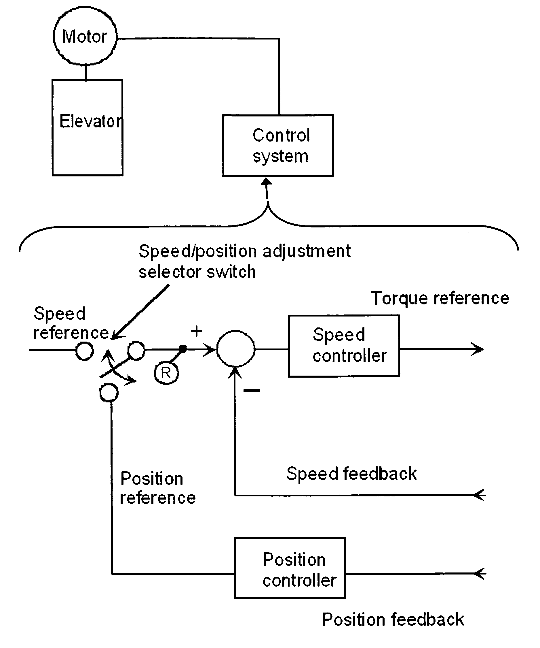
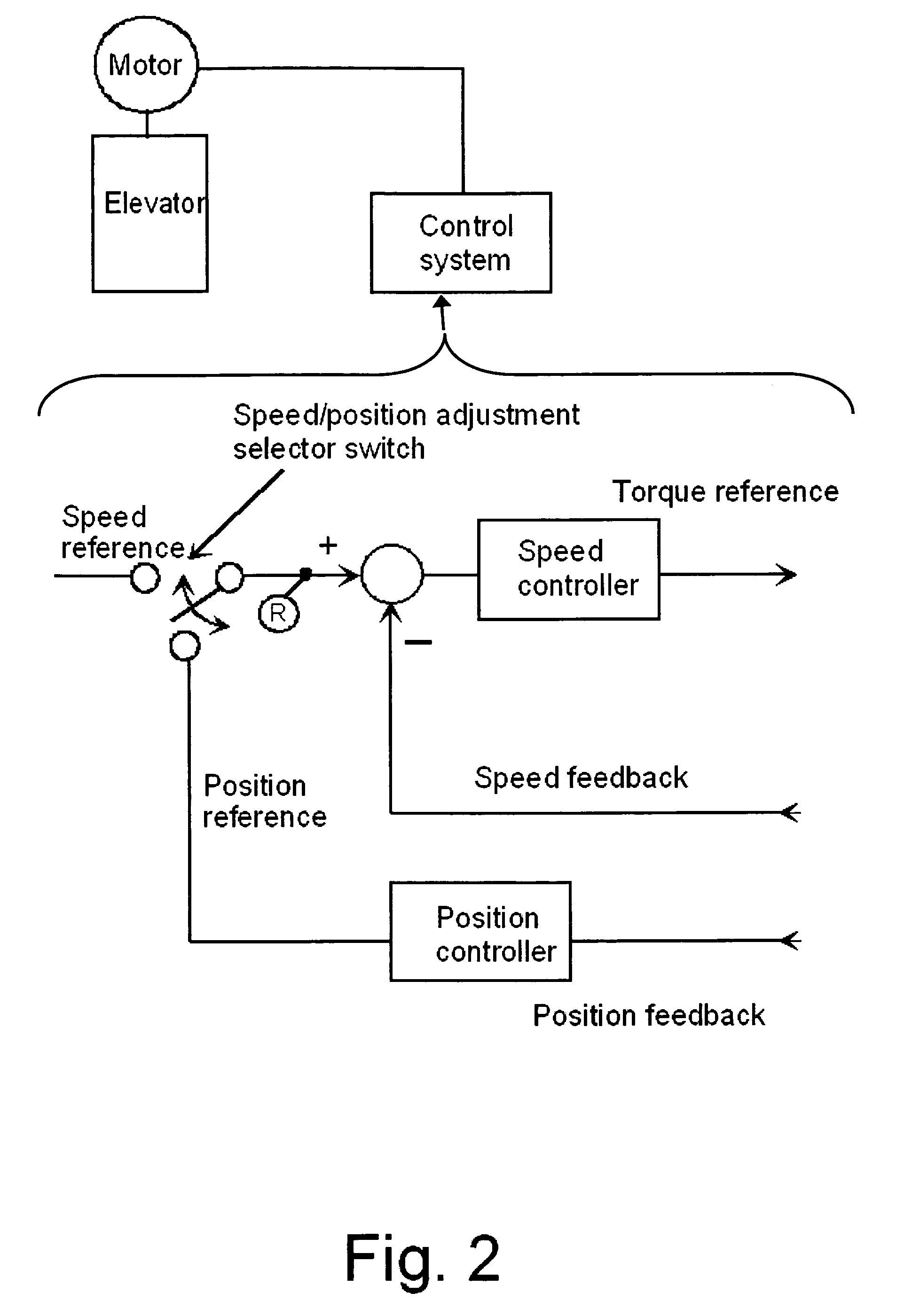
[0009]An aspect of the invention is to develop a new method for controlling an alternating-current motor for use in an elevator, a method that is simple to implement and enables an elevator car to be reliably stopped exactly at a floor level.
[0010]By the solution of the invention, at the final stage before the car stops at the landing, the motor is controlled by using a position reference. This results in a simple and reliable adjustment that is directly dependent on the distance to the desired stopping position. During the rest of the travel curve, a speed reference is observed, thus utilizing the advantages of speed adjustment.
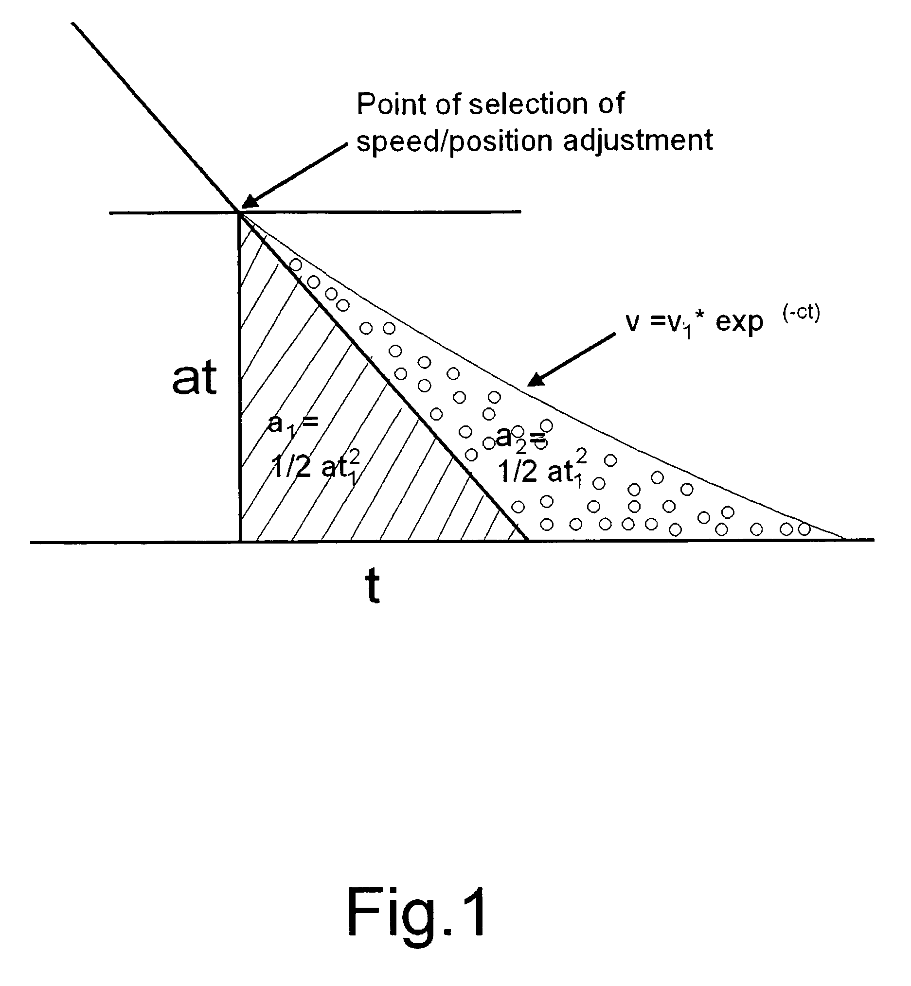
[0014]According to a further embodiment, when the elevator is decelerating, the motor is controlled by a speed adjustment method until a point is reached where the ratio between the acceleration and the speed is the same as the ratio between the remaining distance and the speed, and at this point the control is changed over to position adjustment. In this way, a control method is achieved that is independent of other drive parameters.

Problems solved by technology

However, the solution disclosed in this publication is complicated and it can therefore not be applied in all elevator drives.
However, when torque control is used in an elevator, following the speed reference is difficult because the torque control determines the overall torque of the system.
Increasing the gain increases the torque, but this leads to problems of stability.

Method used


Image

  • Elevator control using switched speed and position
  • Elevator control using switched speed and position
  • Elevator control using switched speed and position

Examples


Embodiment Construction

[0019]According to FIG. 1, in normal operation the elevator travel curve comprises an initial acceleration, a constant acceleration stage, a constant velocity portion, a constant deceleration stage and a final deceleration. At the deceleration stage, the elevator's velocity is reduced with a constant deceleration, which is represented by portion va of the speed curve in FIG. 1. At the constant deceleration stage, as is well known, equation v1=a*t1, where a is deceleration and t is time, applies for velocity, and equation s1=½*a*t12 applies for distance. In other words, when the elevator comes with constant deceleration to a halt, it travels through a distance of s1=½*a*t12 in time t1. If a final rounding is added to the speed curve at the end of the deceleration stage, in which case the change in deceleration, i.e. the jerk is constant, and a jerk value is chosen such that the stopping distance is doubled, i.e. s2=2*s1=a*t12, then the velocity can be resolved. For example, if the ve...


PUM


Abstract

An elevator control method is provided, where the elevator motor is controlled in such manner that the velocity of the elevator follows a speed reference. When the elevator is decelerating, the motor is controlled by a speed adjustment method during the initial deceleration phase, and during the final deceleration phase the motor is controlled by a position adjustment method. The instant of transition from speed adjustment to position adjustment is determined substantially using the elevator speed curve.

Description

[0001]This application is a Continuation of co-pending PCT International Application No. PCT / FI2004 / 000088 filed on Feb. 24, 2004, which designated the United States, and on which priority is claimed under 35 U.S.C. § 120, the entire contents of which are hereby incorporated by reference. This Nonprovisional application also claims priority under 35 U.S.C. § 119(a) on Patent Application No(s). 20020303 filed in Finland on Feb. 27, 2003, the entire contents of which are hereby incorporated by reference.BACKGROUND OF THE INVENTION[0002]1. Field of the Invention[0003]The present invention relates to an elevator control method and to an apparatus for controlling an elevator.[0004]2. Description of the Related Art[0005]In advanced alternating-current elevator drives, the motor is generally controlled by means of a frequency converter, which is used to adjust the torque and rotational speed of the motor. An individual elevator travel may be regarded as consisting of a departure, accelerat...

Claims


Application Information

Patent Timeline
IPC IPC(8): B66B1/24B66B1/40
CPCB66B1/40
Inventor JAHKONEN, PEKKA
Owner KONE CORP
Learn More