

Personal decontamination apparatus and method
a decontamination apparatus and a technology for personal devices, applied in the direction of liquid transfer devices, lighting and heating apparatus, combustion types, etc., can solve the problems of unwieldy operation like an ordinary aerosol dispenser, lack of propellant energy to dispense a large amount, etc., and achieve the effect of rapid topical application of cleansing decontamination wash
- Summary
- Abstract
- Description
- Claims
- Application Information
AI Technical Summary
Benefits of technology
Problems solved by technology
Method used
Image

Examples
first embodiment
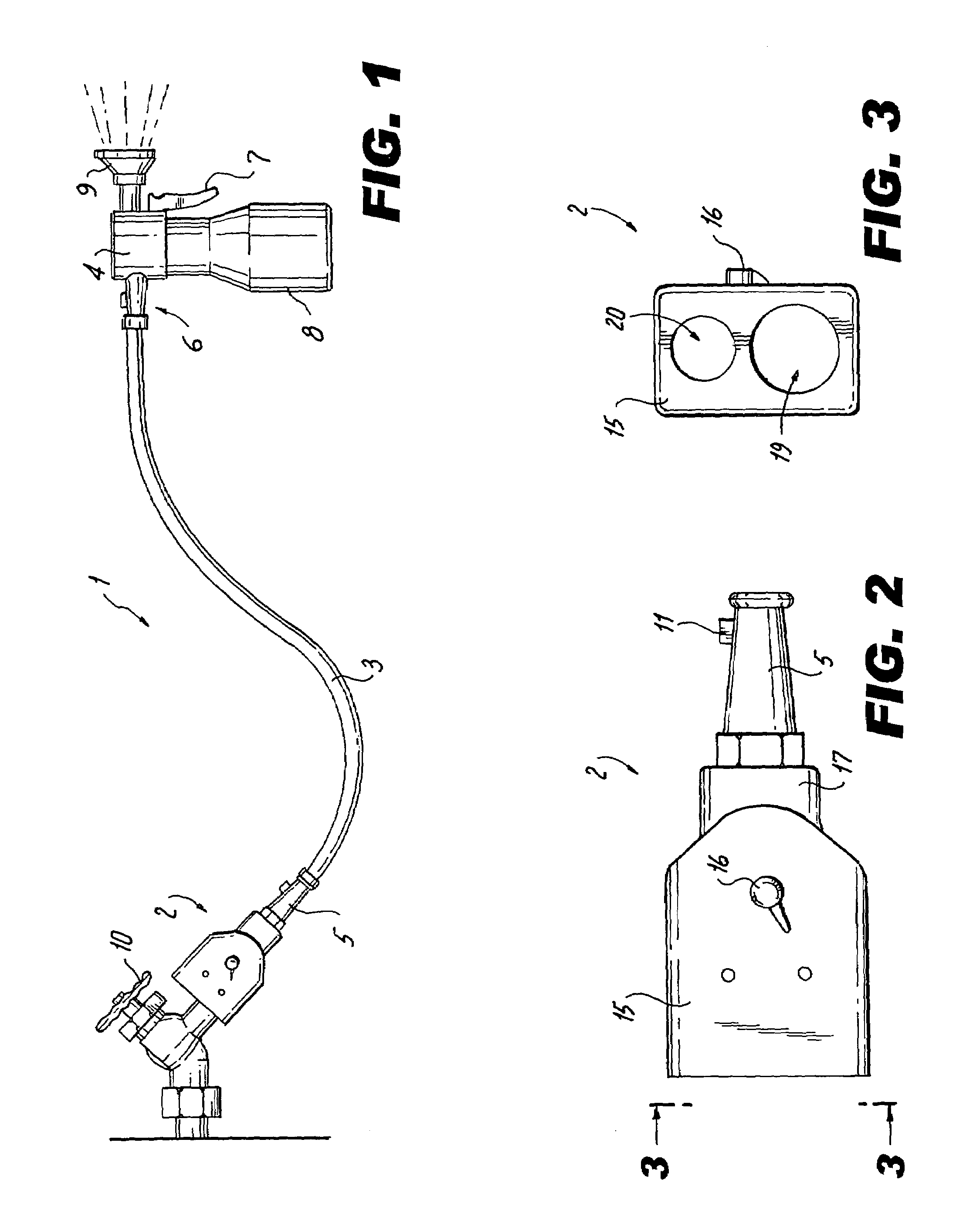
[0029]FIG. 1 shows the first embodiment for a dispenser 1 of this invention which is meant to be connected to a supply of household pressurized water. Here hose spigot 10 is connected to special connector 2 which couples to hose 3 which terminates in decontamination spraying dispenser 4.
[0030]FIGS. 2 and 3 show closer views of special connector 2. Connector 2 has flattened housing 15 with hose coupling female threaded orifice 19 and smaller female threaded orifice 20 sized to couple with a shower head connector. Housing 15 also has a selector valve operated by knob 16 to couple the distal end to either orifice 19 or 20. Housing 17 contains a commercially available cartridge type backflow preventer. Quick disconnect coupling 5 with release button 11 completes special connector 2. The latter can be a straight through HFC 108-35 coupling from Colder Products Company of St. Paul, Minn. The offset placement of threaded orifices 19 and 20, along with the flattened configuration of special...
second embodiment
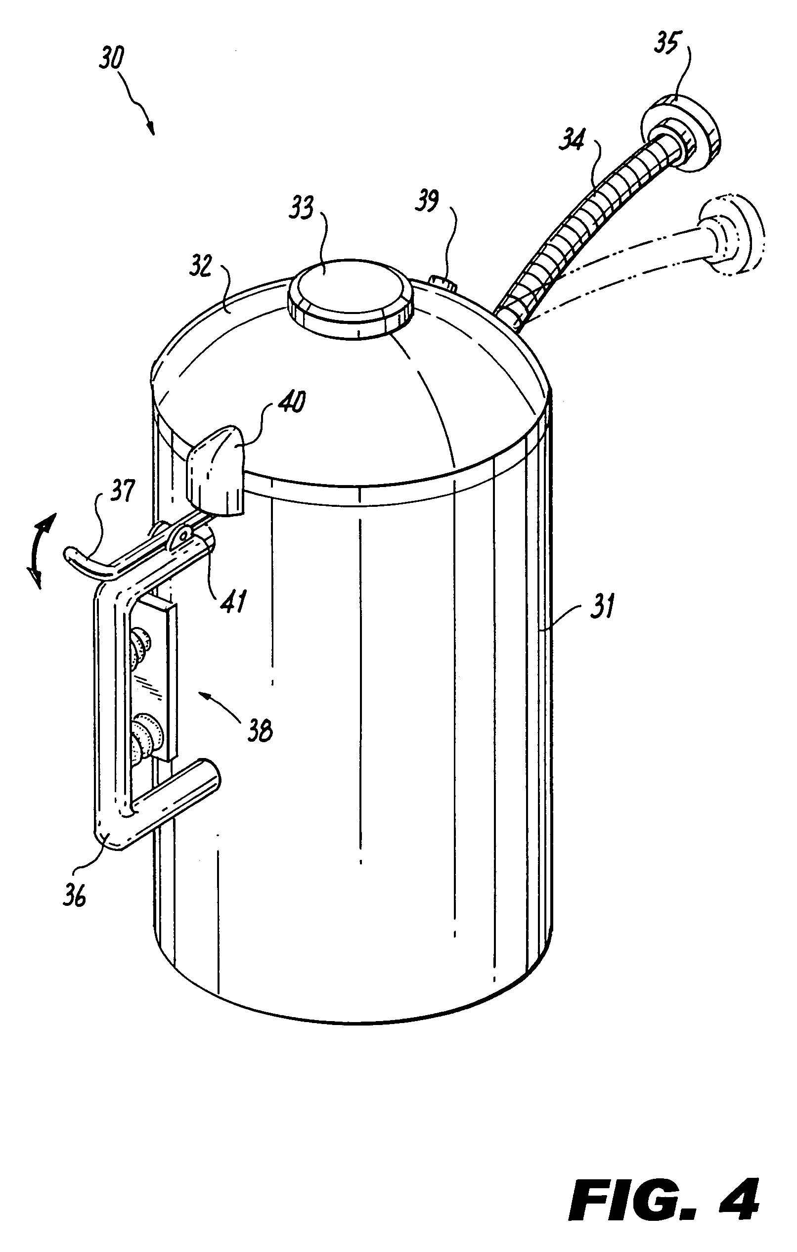
[0031]FIG. 4 shows aerosol dispenser 30 which is this invention used for decontamination in areas not adjacent to pressurized water supply. It includes housing 31, hollow handle 36, compressor assembly 38, cap assembly 32 and locking knob 33. Attached to handle36 is a trigger mechanism, such as, for example, pivot 41 for thumb-operated discharge lever 37. Attached to cap assembly 32 is a fluid output, such as, for example, adjustable gooseneck 34 terminating in nozzle 35, discharge valve coupling cover 40 and inlet venting check valve 39.
[0032]The operation is best understood by reference to the schematic drawing of FIG. 5. Inside housing 31 are two separate compartments or chambers 57 and 58. Preferably one compartment is larger than the other compartment. The larger compartment or chamber 58 is filled with water leaving a small air space on top. The smaller compartment 57 is filled with concentrated decontamination fluid, preferably from a date stamped supply container with a long...
third embodiment
[0035]this invention is illustrated in FIGS. 8 through 10.
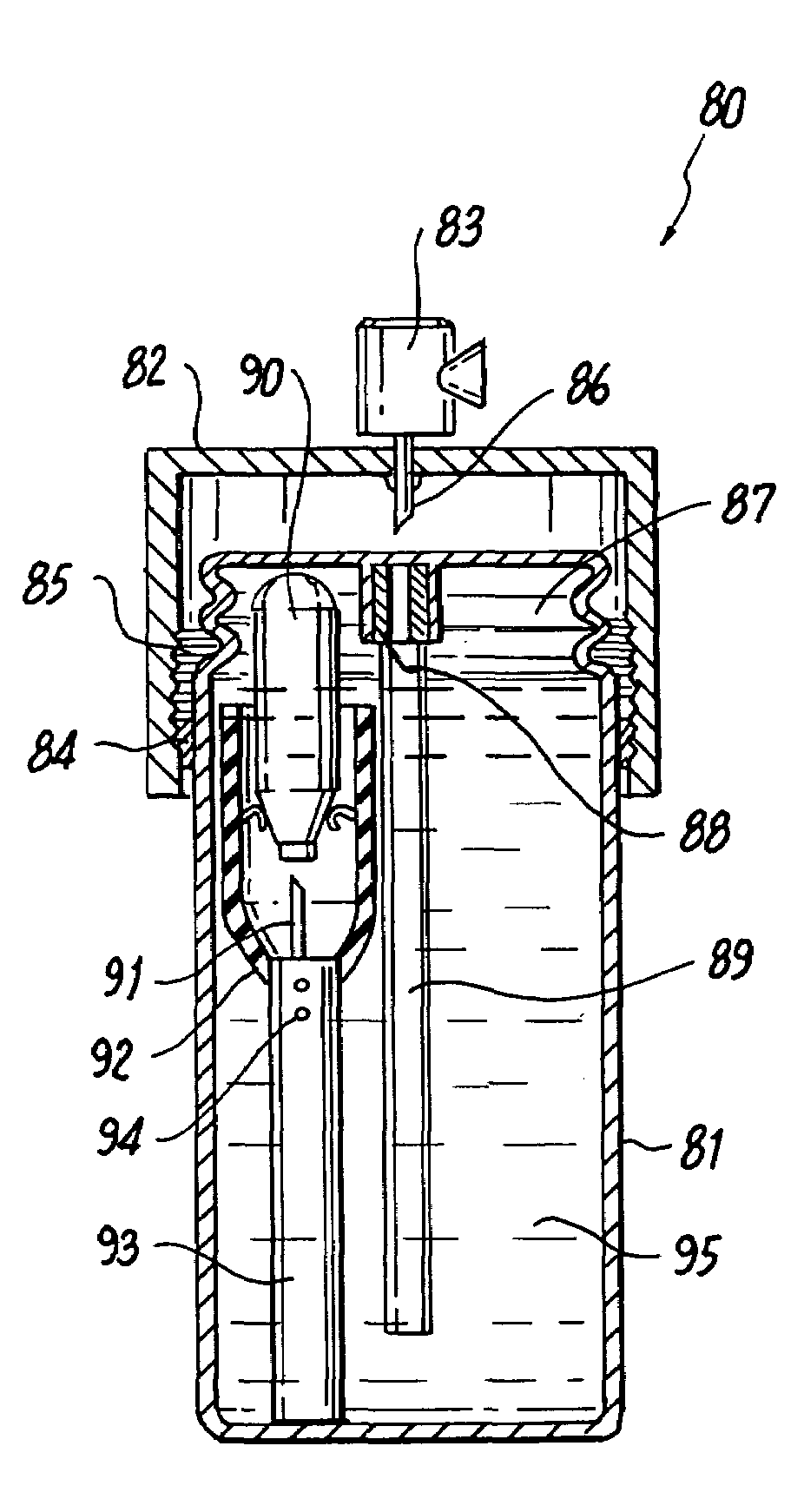
[0036]FIG. 8 shows a long-term storage special hand-held aerosol dispenser 80 with housing 81, discharge valve / nozzle 83, and activating twist cap 82. A frangible tamper evident tape wrap 96 is used to insure integrity of this emergency decontamination dispenser. As distinguished from ordinary aerosols, this is a zero leakage hermetically sealed dispenser designed for long term shelf life storage, rapid robust discharge, and ease of use. The user simply actuates the dispensing of fluid by twisting activator cap 82 several turns and then proceeds to dispense the pre-mixed proper concentration decontamination fluid by pressing discharge valve 83.
[0037]The side view crossection of FIG. 9 shows the preferable operating principle. A robust pressure resistant housing 81 has bellows type convolutions 87 formed in the top section. After all the internal components are mounted and housing 81 is filled with fluid 95, the top is hermeti...
PUM
 Abstract
Description
Claims
Application Information