
Concrete home building

a technology for building homes and homes, applied in the direction of building roofs, girders, joists, etc., can solve the problems of substantial thermal leakage of homes and apartments, and difficult marketability of concrete built homes in colder areas, so as to reduce building costs, eliminate all framing costs, and facilitate erecting

Inactive Publication Date: 2006-12-12
DALTON MICHAEL E
View PDF17 Cites 22 Cited by
  • Summary
  • Abstract
  • Description
  • Claims
  • Application Information

AI Technical Summary

Benefits of technology

[0004]The present invention relates to a concrete building technique that solves the problems of prior approaches. The current system provides a concrete construction technique that is practical for single and multi-family units in cold climates where heating is a significant cost in building operation.
[0006]The building system includes a unique scaffolding system that is stronger, easier to erect and usable by all trades as the exterior of the building is completed. The scaffold system allows for reduced cost to the building during construction and provides a practical method applicable to the ongoing building maintenance.
[0007]The system can eliminate all framing costs typically associated with construction. The system includes a cost effective coating system for the exterior of the structure.

Problems solved by technology

But current concrete construction techniques have made concrete built homes more difficult to market in colder areas.
But current concrete construction techniques lead to homes and apartments that have substantial thermal leaks built in.
These attempts have so far failed to result in a marketable system.
Often the proposed solutions have not been practical or cost effective, producing a building system that either requires a premium price on the market, or a building that is in-efficient to operate, or that requires a major change in the concrete industry and its current construction techniques.
In addition to energy issues, the costs associated with building concrete housing have been somewhat higher then the comparable housing built from wood framing.
The construction industry is very sensitive to price and the cost differential has limited the market for concrete housing.

Method used


Image

  • Concrete home building
  • Concrete home building
  • Concrete home building

Examples


Embodiment Construction

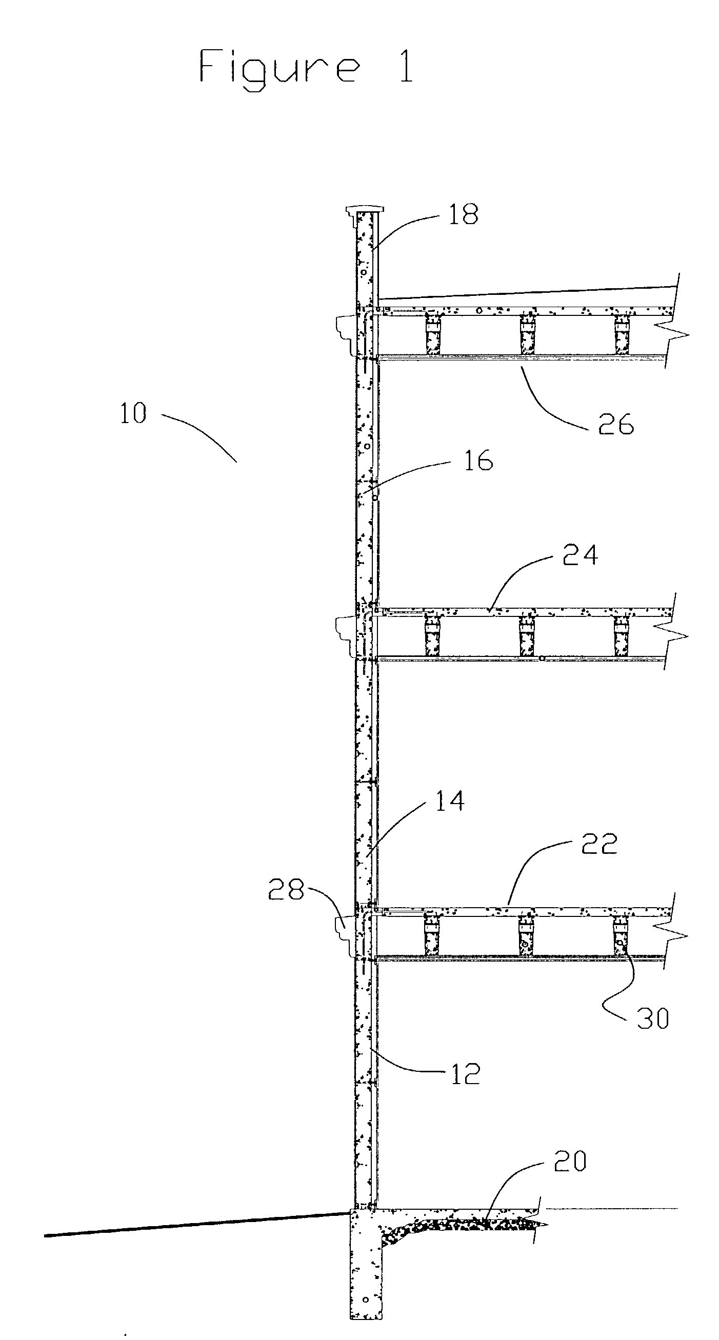
[0020]FIG. 1 shows a partial cross sectional view of the building system (10). In this application there is a concrete wall composed of sections (12,14, and 16) each section defining a level of the building. A parapet wall (18) is formed at the top of the building. There is a first floor (20), two upper floors (22 and 24) and a roof (26). The exterior of the building includes a decorative molding (28) that is mounted on anchors (See FIG. 8) cast in the wall. In this view the concrete joists (30) are shown in cross section.

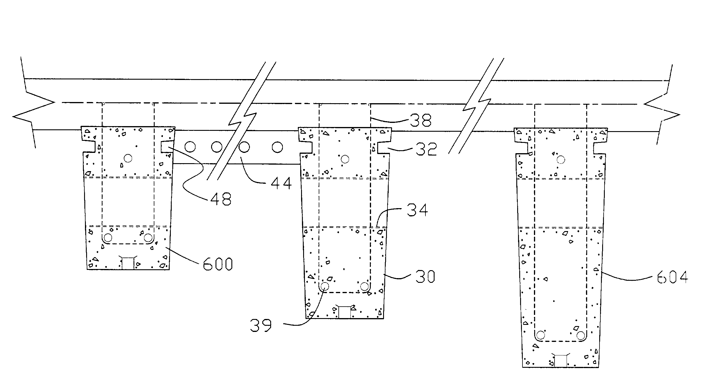
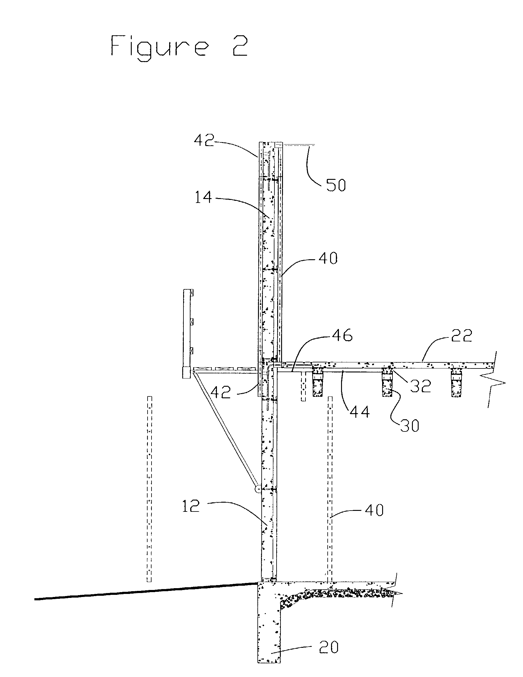
[0021]FIG. 2 shows some of the detail of the construction techniques. In FIG. 2 the first and second walls (12 and 14) as well as the first floor (20) and second floor (22) have been formed. Standard hand set aluminum concrete forms (40, 42 and 44 and 48) are shown. Each wall section requires 4 sets of forms two large forms (40) one on the inside and one on the outside, also one small cap form (42) set on top of the exterior form (40), and a slightly shorter cap fo...


PUM

PropertyMeasurementUnit
lengthaaaaaaaaaa
thermal performanceaaaaaaaaaa
energy efficientaaaaaaaaaa

Abstract

A system of building concrete homes and apartment buildings. The system creates a structure that is well insulated and that is very practical and economical to build. The system uses standard components such as wall ties, concrete forms, rigid foam insulation, and concrete, all of which are readily available in the market today. The system creates a building that is insulated and thermally broken at its structural connections such that use in temperate and colder climates is possible. Presently concrete construction finds only limited use for the construction of single family and multi-family housing. The system is economical to construct when compared to wood frame housing.

Description

BACKGROUND OF THE INVENTION[0001]In the concrete housing industry it is common to build multi-unit apartments and homes in warmer environments. But current concrete construction techniques have made concrete built homes more difficult to market in colder areas. It is common practice to use rigid foam insulation to improve the thermal performance of concrete homes and apartments. In some cases the foam is added to the concrete wall after it is cast, but it is also common to use the foam as part of the form when the concrete is cast and to leave the foam in place after the concrete is cast. But current concrete construction techniques lead to homes and apartments that have substantial thermal leaks built in.[0002]A number of variations have been tried to effectively insulate a concrete building for cold areas. These attempts have so far failed to result in a marketable system. Often the proposed solutions have not been practical or cost effective, producing a building system that eith...

Claims


Application Information

Patent Timeline
Patent Type & Authority Patents(United States)
IPC IPC(8): E04G13/04E04B1/16E04B5/04E04B5/26E04C3/26E04C5/07
CPCE04B1/161E04B5/046E04B5/265E04C3/26E04C5/07
Inventor DALTON, MICHAEL E.
Owner DALTON MICHAEL E
Learn More