System for storing and displaying audio/video works

Inactive Publication Date: 2006-12-12
POLK JONATHAN M
1 Cites 3 Cited by

AI-Extracted Technical Summary

Problems solved by technology

Unfortunately, the small size, offering approximately 14% of the area that an LP offers, makes the inclusion or display of associated photographs, artwork, and other materials problematic.
These boxes are substantially the same size as the CDs and, consequently, they do not lend themselves easily to the inclusion of significant amounts of descriptive matter generally, and descriptive matter media in particular.
Moreover, the compact size of the jewel box makes the storage and organization of larger collections of CDs awkward and unsatisfying to the collector.
Further, it is difficult to maintain the storage order of many small sized containers.
Still further, the jewel box itself is a clumsy container that makes repeatedly accessing the CD frustrating, and there is relatively little display value to these diminutive packages.
At times, one can find particular collections of CD recordings that are released in so-called “box sets,” which often employ collector keepsake packaging in a larger format than that used for individual CD recordings; such box sets, however, serve only to store those specific CDs which are sold in the set (which CDs are generally new compilations of existing recordings, as opposed to the actual albums ...

Benefits of technology

[0013]To enhance effective utilization of the pages, still another embodiment includes places fo...

Abstract

A storage system for holding entertainment-content storage devices such as CDs comprises one or more pages that are combined to form a book of pages, where each of the pages is adapted to store a plurality of such storage device, as well as associated descriptive matter media, such as pictures booklets, etc. More particularly, at least one side of each page includes a plurality of distinct places for inserting and, thereby storing, the storage devices, and physically proximate means for storing descriptive matter media. In one embodiment, for example, the places for inserting and storing storage devices in each page comprises four generally circular cavities having their centers lying on a circle that is centered on a page, and a covering that partially covers the circular cavities. Each circular cavity is dimensioned to hold a CD (or DVD) and the partial covering of the circular cavity is adapted to insure that a CD will rest securely in the circular cavity. The covering is adapted to also hold collectible keepsake items, such as a concert ticket, or a lyrics booklet.

Application Domain

Apparatus modification to store record carriersToys +9

Technology Topic

Circular cavityAudio frequency +1

Image

  • System for storing and displaying audio/video works
  • System for storing and displaying audio/video works
  • System for storing and displaying audio/video works

Examples

  • Experimental program(1)

Example

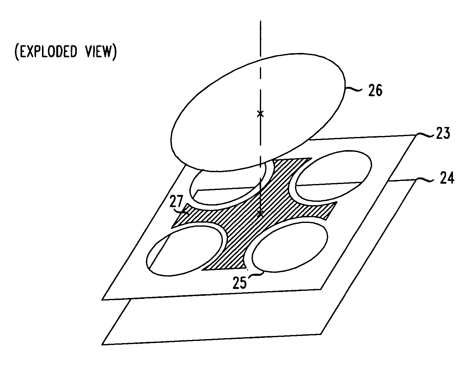
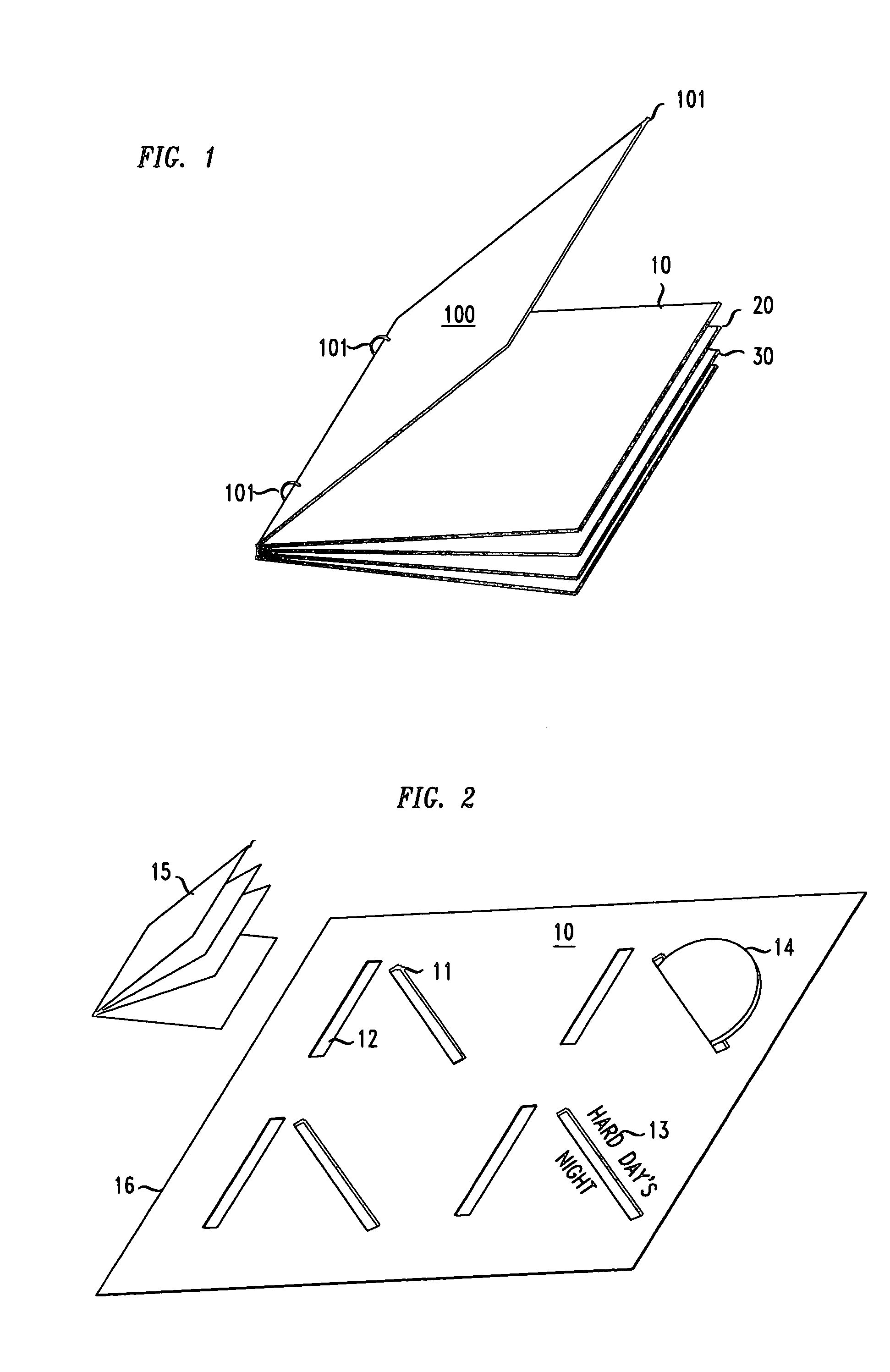
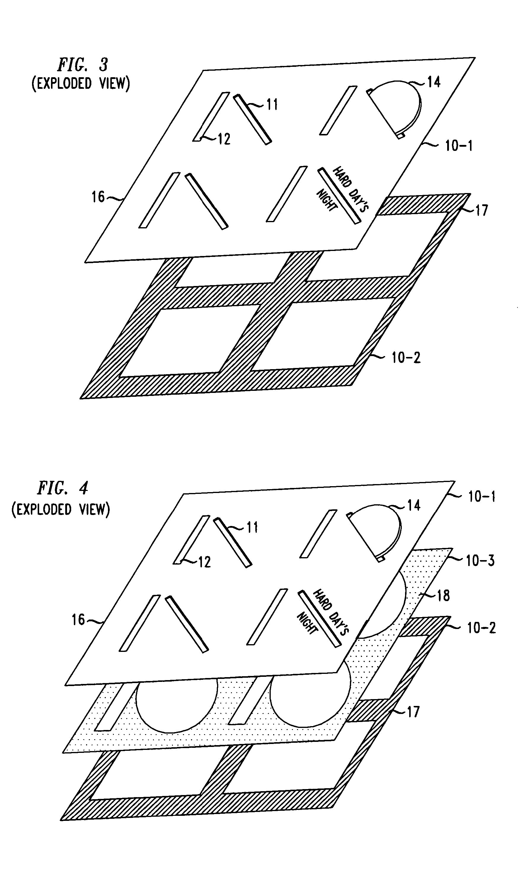
[0023]This invention provides a collectible keepsake book-like storage system for storing discrete collections of CDs, DVDs, or other entertainment-content storage devices and associated descriptive media. This system may be pre-customized, for example, for storing the CD-based media relating to a specific artist or subject, it can be customized by the user of the system, or it can form a general storage system. The book-like storage system typically comprises a plurality of pages having a novel construction that includes specific locations for inserting the entertainment content storage devices and for inserting associated descriptive media. In its customized embodiment, at least some of the locations for holding the storage devices include an identifier to assist the user in the organizing of the user's storage device, such as CD, and associated descriptive matter media, such as booklets, pictures, listing of song titles, lyrics, etc. The identifier may be a label, a picture, etc.
[0024]FIG. 1 shows a perspective view of a storage system 100, accord with the principles disclosed herein, that is binder-like. It includes a cover page 101, internal pages 10, 20 and 30, and rings 101 that hold the pages between top cover page 101 and a bottom cover page (not labeled). Rings 101, which may be conventional note-book binder rings, allow the user of system 100 to add or delete pages from system 100. Of course, system 100 can be constructed to be book-like, in the sense that it has a fixed number of pages that are attached to a spine between the outer covers of the book, obviating the need for rings 101 or any other means for adding or deleting pages from the storage system.
[0025]FIG. 2 presents the top view of an illustrative page within system 100. As illustrated, page 10 comprises four diagonal slits for inserting CDs or DVDs. These slits are arranged on a diagonal to allow for easy handling of CDs during insertion or retrieval of the CDs but, of course, the precise angle of the slits is not critical. When edge 16 is the edge that is attached to the spine of system 100, I found it advantageous for the angle of the slit to be between 90 degrees and 180 degrees, with the reference 0 degrees extending to the right from edge 16 (as depicted in FIG. 2, the angle is approximately 135 degrees).
[0026]In physical proximity to each CD-holding slit 11, page 10 includes slits 12 that are designed to allow the user to insert one or more descriptive media. This may include a CD booklet, a photograph, a concert ticket, etc. In the case of booklet 15, for example, the user of system 100 might insert all but the first page of booklet 15 into slit 12.
[0027]Finally, for embodiments where page 10 is pre-customized to a particular collection of CDs, for example, songs of “The Beatles,” one or more of the areas that are proximate to a diagonal slit and a vertical slit (as depicted in FIG. 2) includes an indicator, or identifier, such as label 13, to assist the user of system 100 to insert the proper CD into the associated CD-holding slit 11. Of course, the identifier can be much more elaborate than the one depicted in FIG. 2, such as a replica of the artwork that is found on a purchased CD, or depicted on the jewel case of the purchased CD.
[0028]When slits 11 of page 10 are made slightly shorter than the diameter of CDs 14, and page 14 is page of a somewhat rigid material (such as cardboard, or plastic), there is no need to include retaining means for CDs 14. In normal handling of system 100, frictional forces tend to keep CDs 14 lodged within slits 11. However, if slits 11 and 12 extend all the way through page 10, then the backside of page 10 would show those portions of CDs 14 and descriptive matter items (such as booklet 15) that were inserted into the corresponding slit. This is not terribly attractive, so I found it advantageous to construct an arrangement whereby the slits extend only partially into page 10, and page 10 includes spaces within the page that are coupled to the slits, and accommodate the portions of CDs 14 and descriptive media (e.g. booklets 15) that are inserted into slits 11 and 12, respectively.
[0029]The construction of page 10 so that slits 11 and 12 extend only partially into the page and are the ingress and egress venues for the holding spaces within page 10 can take numerous forms. When constructed from plastic material, a mold can be employed that creates page 10 so as to include slits 11 and 12, and the associated enclosed spaces within the page. Alternatively (and particularly when constructed from sheets (e.g., paper, cardboard, plastic, etc.), page 10 can be constructed by joining a number of plies. Illustratively as shown in FIG. 3, page 10 comprises a first ply (10-1) that include slits 11 and 12, and a second ply (10-2) that is solid. The solid ply is attached to the first ply (e.g., glued, sewn, molded into) at least around the perimeter of the page and, preferably, also in the region between the sets of slits. This is illustrated in FIG. 3, where the two plies are glued to each other along crosshatched area 17 that covers the perimeter of page 10 and two stripes that cross each other at the center of the page.
[0030]It may be realized that the arrangement of slits 11 and 12, even with addition of the second ply, can present a bit of a problem when both a CD and an associated booklet are stored, because some portion of CD 14 that is on the inside of slit 11 can interfere with some portion of the back page of booklet 15 that is on the inside of slit 12. To avoid this possible interference, page 10 can include partially, or completely, separable spaces that are associated with slits 11 and slits 12. One embodiment that provides for such separate spaces, shown in FIG. 4, includes a third ply (10-3) that is interposed between plies 10-1 and 10-2 and glued to the ply 10-1 throughout an area, such as the stippled area 18. Note that in an area below slits 12, ply 10-3 is not glued to ply 10-1, to allow the descriptive matter media that is inserted in to slits 12 to be held within a cavity that is formed between plies 10-3 and 10-2.
[0031]FIG. 5 depicts two additional, alternative, arrangements that prevent interference between that which is inserted in slits 11 and that which is inserted into slits 12. Element 19 in FIG. 5 is a piece of paper (or any other sheet material) that is glued at its periphery to the underside of ply 10-1 of sheet 10. The gluing of element 19 around its periphery creates a pocket that is accessible through the slit (11) in the top side of ply 10-1. Alternatively, a flap 21 may be included in the underside of ply 10-1 that extends from each slit 12 toward the associated slit 11. Flap 21 guides both the CD that is inserted into slot 11, as well as booklet 15 that is inserted into slit 12, in such a manner that the CD is on one side of the flap, and the booklet is on the other side of the flap. Consequently, the booklet and the CD do not interfere with one another.
[0032]The above description relates to the storing of CDs on one side of page 10. In situations where it is desirable to have fewer pages in the FIG. 1 system, it is advantageous to store CDs and associated descriptive media on both sides of each page. This is achieved easily by constructing each page with a center layer, and additional layer sets on each side of the center layer. Each layer set provides for the storage of CDs and associated descriptive matter media, as described above. Illustratively, a page may comprise a center layer 10-2, with each layer set comprising an outside layer 10-1 and an interposed layer 10-3.
[0033]FIG. 6 presents yet another alternative embodiment. Instead of including slits 11 in page 10, with an attendant space, or pocket, within page 10, the FIG. 6 embodiment includes generally triangular pieces (paper, plastic, etc.) that are attached (for example, glued) to the outer layer(s) of page 10 along the two mutually orthogonal sides of the triangular pieces. This results in triangular-shaped pockets into which CDs can be inserted (although the shape of the pocket can be rounded, or any other shape that will hold a disc in place).
[0034]FIG. 7 presents another embodiment (in exploded view) for pages in the FIG. 1 storage system. In connection with the placement of CDs and DVDs, each page includes four cylindrical cavities that are created by joining ply 23 that contains four holes 25 with ply 24. The four holes have their centers on a circle that is centered on the page, or slightly offset away from the edge of the page that attached to the spine of FIG. 1 storage system. As depicted, the centers are equally spaced around such a circle (which means that lines that join alternate circle centers form two mutually orthogonal lines). In embodiments where CDs are stored on both sides of a page, ply 24 represents the center ply, and the page contains an outer ply 23 on each side. The thickness of ply 23 is chosen to approximately equal the thickness of CDs.
[0035]To hold the CDs that may be placed within the resulting cylindrical cavities defined by circles 25, the FIG. 7 embodiment includes a disc 26 that is approximately centered about the set of four cylindrical cavities, and attached to ply 23, illustratively, throughout hatched area 27. What results is a set of four quarter-circle sectors of disc 26 that partially cover the cylindrical cavities. The partial cover of the cavities provides a mechanism that allows insertion and extraction of CDs from the cylindrical cavities, while at the same time prevents the CDs from falling out of the cylindrical cavities of their own volition. For embodiments where it is desirable to see whatever is written or otherwise shown on the CDs, disc 26 is advantageously made of a transparent plastic. Whatever material is used, it needs to be rigid enough to hold the CDs, yet pliable enough to allow a person to easily extract a CD from the cylindrical cavity.
[0036]FIG. 8 shows the FIG. 7 arrangement not in exploded view, and also it depicts a variation thereof. Specifically, the FIG. 8 arrangement includes circular indentations 28 in each of the cylindrical cavities. Indentations 28 facilitate reaching the edge of a CD so that it can be removed from the cylindrical cavity more easily.
[0037]Descriptive materials, such as concert tickets, or a CD booklet can be inserted inside the flaps created by the disc sectors (over the CDs) but that creates a slight interference situation, in that it may be somewhat awkward to remove a CD from its cylindrical cavity without removing the descriptive material. FIG. 9 presents a modified embodiment that overcomes this difficulty. It includes, a disc 29 that, illustratively, is smaller in diameter than the diameter of disc 26 and co-centered therewith. Disc 29 is attached to disc 26 along a cross-like region not unlike region 27, forming sector flaps that can hold descriptive material. Disc 29 may be constructed from a transparent plastic material like that of disc 26, and the two discs can be molded to each other. Alternatively, discs 29 and 26 can be attached to ply 23 through a sewing operation, heat-sealing, or other operation with the same effect. FIG. 10 shows the unexploded view of the FIG. 9 arrangement, with a sewn attachment of discs 29 and 26 to ply 23, and with a CD 25 and a CD booklet 33 shown inserted.
[0038]FIG. 11 presents yet another embodiment for pages of the FIG. 1 system. It includes quarter-circle sectors 31 that are attached to the four corners of page 10 for storing the descriptive materials (such as booklet 33). In the center of the page, there are two discs 37 and 38 (for example, plastic) that are sewn together and to the page in a cross pattern (as depicted by the dashed lines) to form four pouches. Each pouch is associated with a corner, and is capable of storing a CD, such as CD 25.
[0039]FIG. 12 presents still another embodiment for pages of the FIG. 1 system. It includes four hinged sleeves 34 that pivot about a line that is different from a line about which the entire page pivots, with openings 35 at the edge away from the hinged side, through which CDs can be placed within the sleeves. Descriptive matter can be inserted in the cavities of the page, below the hinged sleeves, and labeling information that assists in organizing the storage of devices in the system can be placed on the outside face of the sleeves, as well as around the sleeves.
[0040]The above descriptions disclose various embodiments of the storage system disclosed herein. It should be understood that various modifications to the disclosed embodiments can be created by a skilled artisan without departing from the spirit and scope of the invention defined in the following claims.

PUM

no PUM

Description & Claims & Application Information

We can also present the details of the Description, Claims and Application information to help users get a comprehensive understanding of the technical details of the patent, such as background art, summary of invention, brief description of drawings, description of embodiments, and other original content. On the other hand, users can also determine the specific scope of protection of the technology through the list of claims; as well as understand the changes in the life cycle of the technology with the presentation of the patent timeline. Login to view more.
Why Eureka
Try Eureka