Filter cover assembly for an air conditioning unit

Inactive Publication Date: 2006-12-12
HANON SYST
View PDF1 Cites 35 Cited by
  • Summary
  • Abstract
  • Description
  • Claims
  • Application Information

AI Technical Summary

Benefits of technology

[0014]Accordingly, the present invention has been made keeping in mind the above problems occurring in the prior art, and an object of the present invention is to provide a filter cover assembly for air conditioning units which is prevented from interf

Problems solved by technology

As the air filter has been used for a lengthy period, an excessive amount of impurities is deposited on a filtering surface of the filter, thus increasing the air flowing resistance and reducing the air blowing efficiency of the blower fan.
However, since the hook part 514 perpendicularly extends rearward from the upper edge of the cover body 51, the hook part 514 may often interfer

Method used


Image

  • Filter cover assembly for an air conditioning unit
  • Filter cover assembly for an air conditioning unit
  • Filter cover assembly for an air conditioning unit

Examples


first embodiment

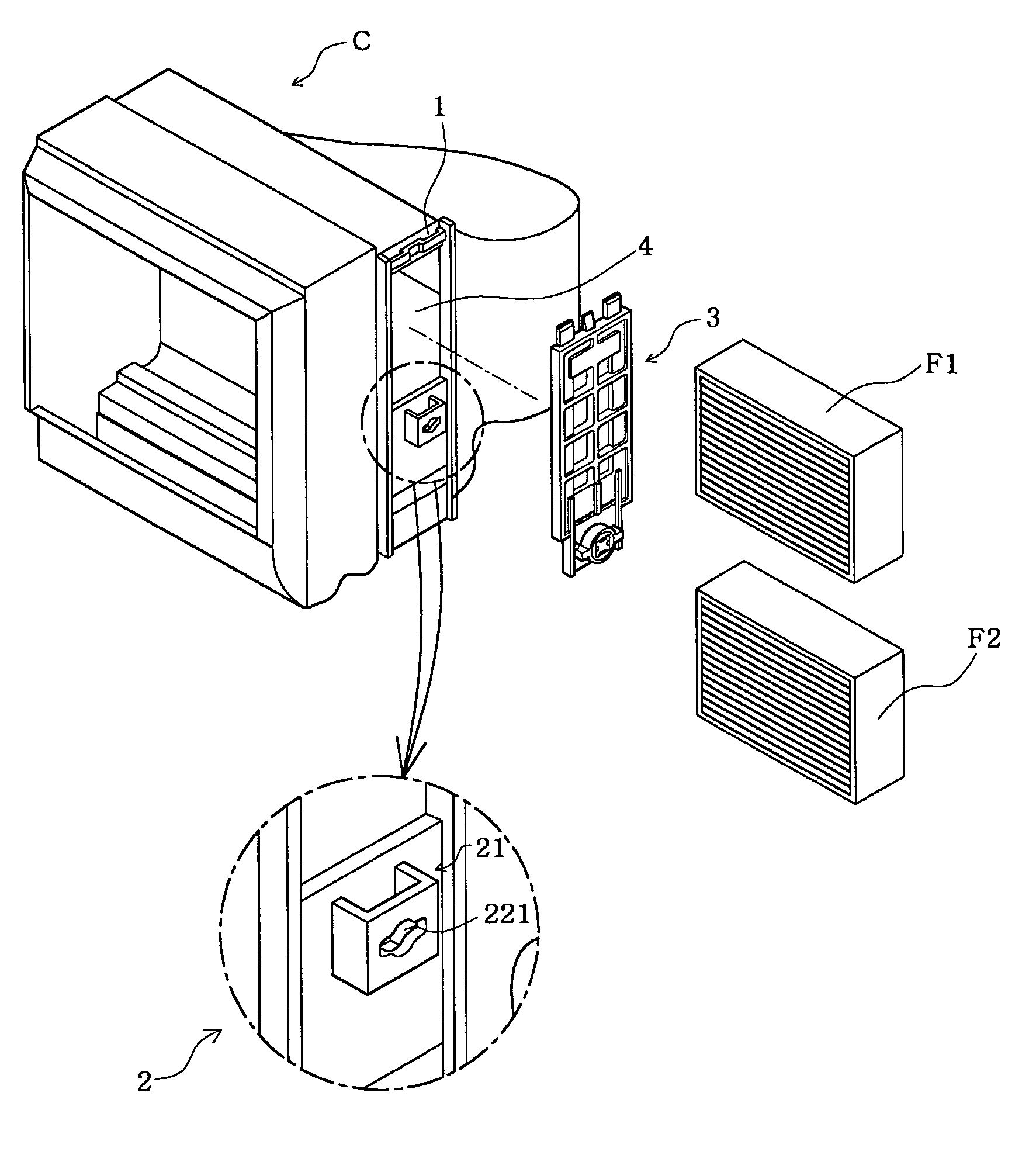
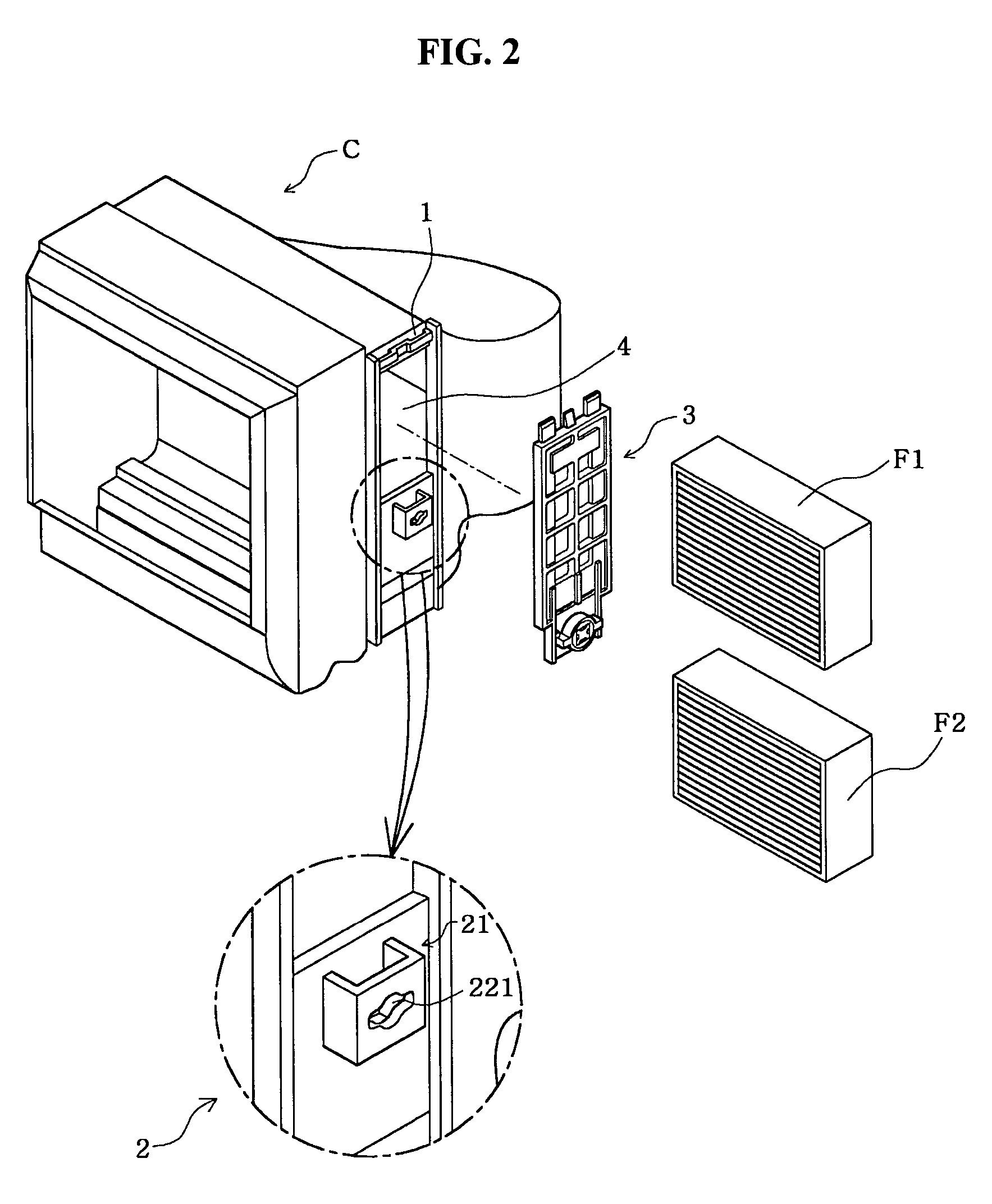
[0027]The second filter cover 2 includes a cover body which is integrally formed on a side surface of the casing C of the blower unit to close a lower part of the opening 4. The second filter cover 2 further includes a engaging part to engage with the rotary fastening unit 32 and fasten the first filter cover 3 to the first filter cover 2. In the first embodiment, the engaging part comprises a locking bracket 21 which is provided on the cover body of the second filter cover 2 to engage with the locking member 322 of the rotary fastening unit 32. A fitting slot 1 is provided on the side surface of the casing C at a position above the opening 4 to receive the fitting protrusion 311 of the first filter cover 3 therein.

[0028]The rotary fastening unit 32 comprises a rotary knob 321, the locking member 322 and the shaft 323. The shaft 323 connects the rotary knob 321 to the locking member 322 into a single body while spacing the rotary knob 321 and the locking member 322 apart from each o...

second embodiment

[0037]FIG. 7 shows the construction of a filter cover assembly for air conditioning units, according to the present invention.

[0038]In the second embodiment, the second filter cover 2 is constructed so that the cover 2 is separated from a casing C of a blower unit, different from the first embodiment.

[0039]The construction of the filter cover assembly according to the second embodiment will be described with reference to FIGS. 3A, 3B and 7. In the filter cover assembly according to the second embodiment, a joining part 23 having a slot 231 extends downward from a lower edge of the second filter cover 2 to be detachably locked to the casing C of the blower unit. The second filter cover 2 further includes a engaging part which comprises only a hole 221 provided at an upper portion of the second filter cover 2. The hole 221 has a shape corresponding to the locking member 322 of the rotary fastening unit 32, so that the locking member 322 is locked to the second filter cover 2 through t...


PUM


Abstract

A filter cover assembly for an air conditioning unit is disclosed. The filter cover assembly allows a user to easily install a filter in a casing of an air conditioning unit through an opening provided on the casing and to easily remove and mount the filter cover assembly from and to the opening of the casing, so that the user can conveniently exchange the filters. The filter cover assembly is mounted to the opening of the casing of the air conditioning unit to close the opening, with a filter installed in the casing to remove impurities from air flowing into the air conditioning unit. The filter cover assembly includes a first filter cover, a second filter cover and a rotary fastening unit to fasten the first filter cover to the second filter cover.

Description

BACKGROUND OF THE INVENTION[0001]1. Field of the Invention[0002]The present invention relates, in general, to filter cover assemblies for an air conditioning unit and, more particularly, to a filter cover assembly for air conditioning units which allows a user to easily install a filter in a casing of an air conditioning unit through an opening provided on the casing, and to easily remove and mount the filter cover assembly from and to the opening of the casing, so that the user can conveniently exchange the filters when necessary.[0003]2. Description of the Prior Art[0004]Filters are important elements that are installed in a variety of fluid paths to remove impurities from fluids, such as air or water, flowing through the fluid paths with minimum flowing resistance and maximum filtering efficiency. Particularly, an air filter used in an air conditioning apparatus of a vehicle is installed at a predetermined position within an air flowing path of the air conditioning apparatus to r...

Claims


Application Information

Patent Timeline
IPC IPC(8): B01D35/30B60H3/06B01D46/00B60H1/00F24F13/28
CPCB01D46/0005F24F13/28B01D2265/02B01D2265/06B60H2001/00621B60H3/06
Inventor LEE, HEON-GU
Owner HANON SYST
Why Eureka
Try Eureka