Light emitting device having integrated rectifier circuit in substrate

a technology of rectifier circuit and light emitting device, which is applied in the direction of basic electric elements, semiconductor devices, electrical equipment, etc., can solve the problems of significant amount of electrical energy being converted into heat, damage to led, and waste of process energy

Active Publication Date: 2006-12-12
TYNTEK
View PDF4 Cites 51 Cited by
  • Summary
  • Abstract
  • Description
  • Claims
  • Application Information

AI Technical Summary

Benefits of technology

[0009]Accordingly, the present invention provides a novel light emitting device having an integrated rectifier circuit and a related fabrication method, which does not require the installation of individually reversed diodes and LEDs to the substrate, or the wire-bonding of the diodes and LEDs on the substrate.

Problems solved by technology

However, if an AC voltage is applied on a LED, the LED would be damaged if an excessive reverse-biased voltage is exerted across the LED.
The solution is effective but the price to pay is that a significant amount of electrical energy is converted to heat and wasted in the process.
Another problem associated with driving LEDs with an AC voltage is that the LEDs would be lit only during the half cycle that the LEDs are forward-biased.
The two approaches are all too complicated, contributing to rather lengthy production time and high production cost.

Method used


Image

  • Light emitting device having integrated rectifier circuit in substrate
  • Light emitting device having integrated rectifier circuit in substrate
  • Light emitting device having integrated rectifier circuit in substrate

Examples


Embodiment Construction

[0029]The following descriptions are exemplary embodiments only, and are not intended to limit the scope, applicability or configuration of the invention in any way. Rather, the following description provides a convenient illustration for implementing exemplary embodiments of the invention. Various changes to the described embodiments may be made in the function and arrangement of the elements described without departing from the scope of the invention as set forth in the appended claims.

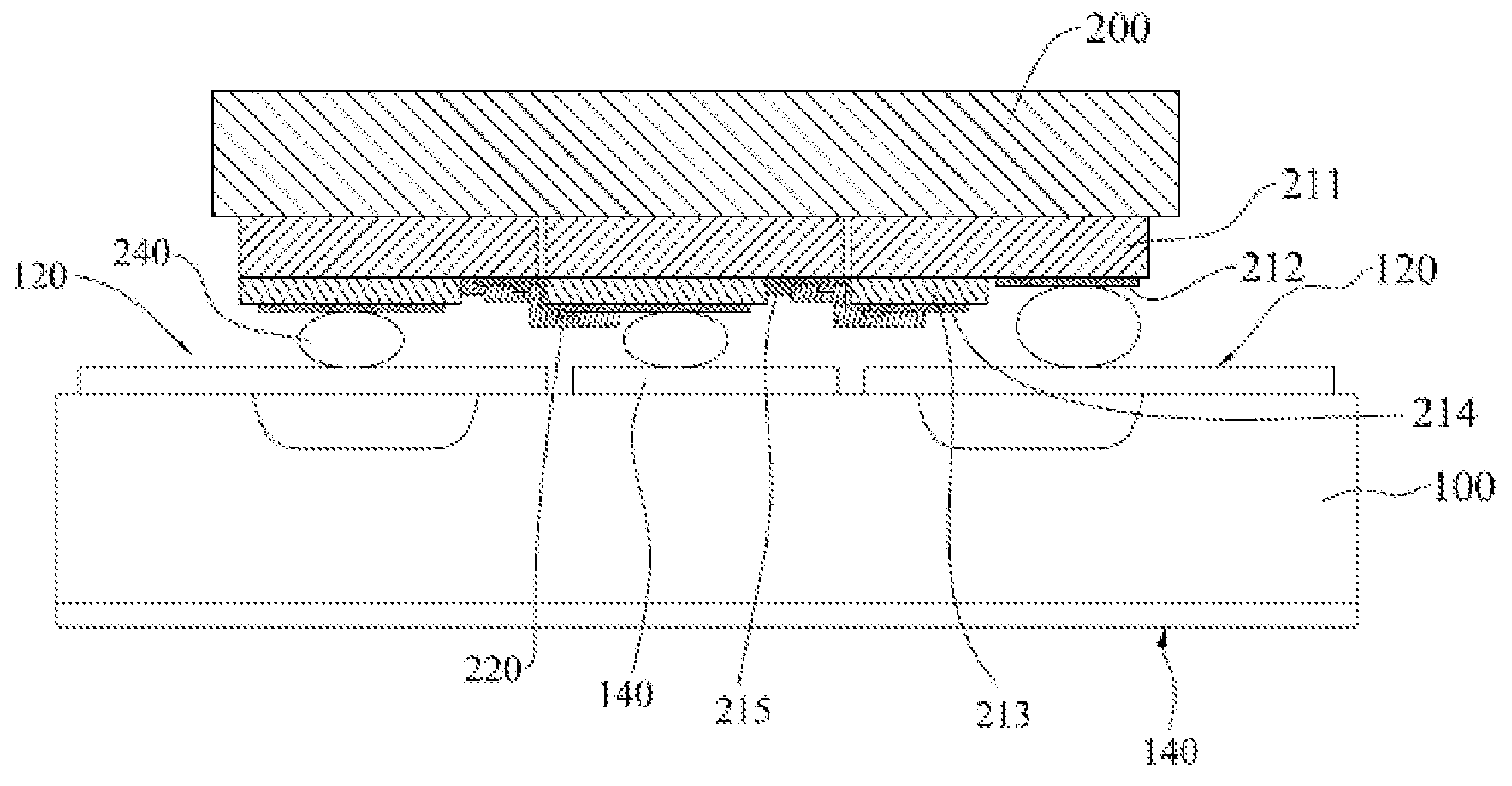
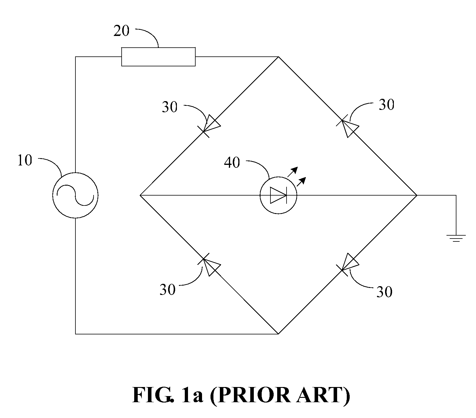
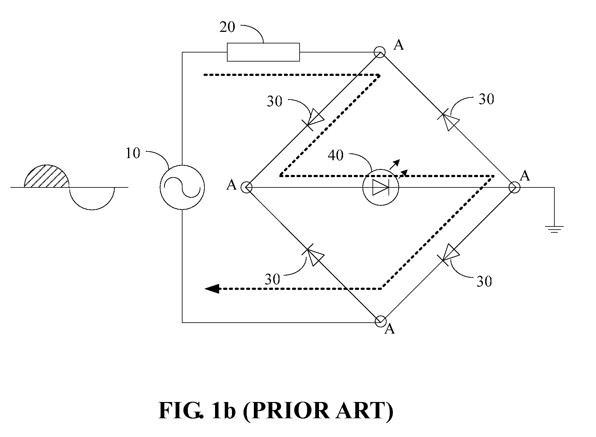
[0030]A LED-based light emitting device having integrated rectifier circuit driven directly by an AC voltage and a related fabrication method are provided herein. Please note that the rectifier circuit being integrated could be a bridge rectifier circuit or other full-wave or half-wave rectifier circuit. In other words, the present invention does not require the rectifier circuit to be of a specific type. Please also note that the subject matter of the present invention is not the circuitry constitu...


PUM


Abstract

A LED-based light emitting device having integrated rectifier circuit driven directly by an AC voltage and a related fabrication method is provided herein. The light emitting mainly contains a lower substrate and an upper substrate. The lower substrate has a built-in rectifier circuit and appropriate electrical contacts of the rectifier circuit are exposed on the top surface of the lower substrate. The upper substrate contains multiple LEDs arranged in an N×M array and the LEDs are all electrically insulated from each other. Metallic plating techniques are applied to establish electrical connection between these LEDs so that they jointly form a circuit matching the rectifier circuit on the lower substrate. The two substrates are faced towards each other and metallic bumps are applied to connect the LED circuit on the upper substrate to the rectifier circuit on the lower substrate, completing a fully function light emitting device.

Description

BACKGROUND OF THE INVENTION[0001]1. Field of the Invention[0002]The present invention generally relates to light emitting devices using light emitting diodes, and more particularly to a light emitting device having a rectifier circuit integrated in the substrate and a related fabrication method thereof.[0003]2. The Prior Arts[0004]In general, an appropriate forward-biased DC voltage is applied to a light emitting diode (LED), and photons are thereby released as the electrons and holes of the LED are driven and re-combined with each other. Recently, as the applications of LEDs are extended to home and outdoor lighting applications, there are increasing demands for directly driving LEDs using AC voltages. However, if an AC voltage is applied on a LED, the LED would be damaged if an excessive reverse-biased voltage is exerted across the LED. A common solution is to adopt a transformer or a voltage reduction circuit or the like to reduce the level of the AC voltage so that the LED can w...

Claims


Application Information

Patent Timeline
Patent Type & Authority Patents(United States)
IPC IPC(8): H01L27/15
CPCH01L25/167H01L27/156H01L2924/0002H01L2924/00
Inventor HUANG, KUO-JUICHOU, WEN-LONGSUNG, CHIA-PIN
Owner TYNTEK
Why Eureka
Try Eureka