
Easy-maintain rear projection television

Inactive Publication Date: 2006-12-12
CORETRONIC
View PDF9 Cites 9 Cited by
  • Summary
  • Abstract
  • Description
  • Claims
  • Application Information

AI Technical Summary

Benefits of technology

[0006]One object of the invention is to provide an easy-to-maintain rear projection television having a casing with a plurality of maintenance holes for quickly dismounting and repairing components inside the television.
[0007]Another object of the invention is to provide an easy-to-maintain rear projection television that allows repairing without changing the locations of its rear cover or front frame, thereby saving the maintenance labor and simplifying the repair process.
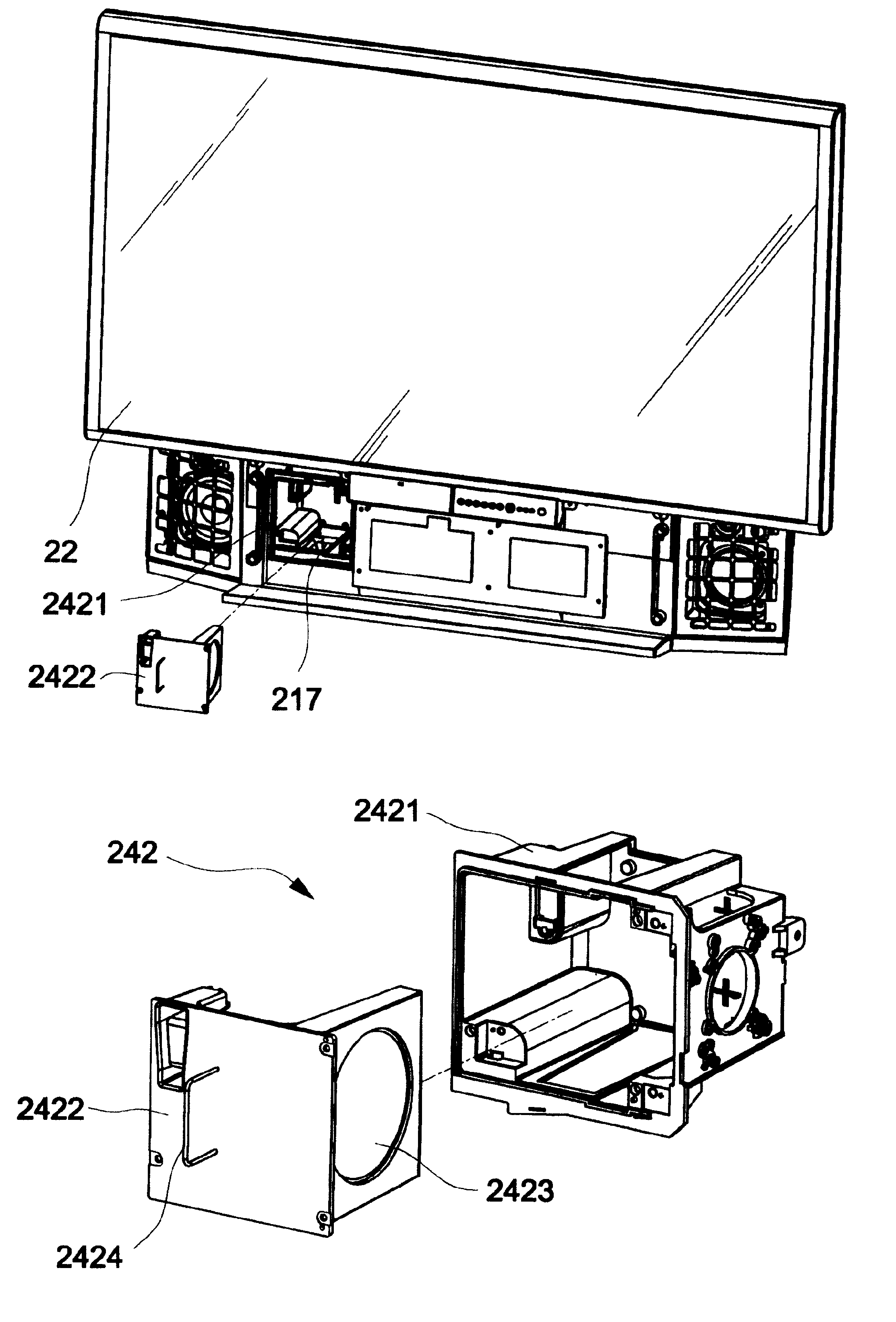
[0008]Furthermore, another object of the invention is to provide an easy-to-maintain rear projection television that includes an electronic unit, an optical module and a set of bulbs that can be replaced without affecting the light projection path.

Problems solved by technology

However, such a lamp has high power consumption and a short service life.
Therefore, the lamp needs to be replaced frequently.
Furthermore, a circuit board and a power supply respectively consist of electric devices that may be defective and damaged after use for a period.
Such a repair method has to change the position of the light engine, the reflector and the screen, adversely affecting the light path.
Moreover, frequently moving the light engine tends to damage the electric devices and optical elements inside the casing.
As the rear projection television becomes increasingly larger, it requires more repair space and labor expertise.

Method used


Image

  • Easy-maintain rear projection television
  • Easy-maintain rear projection television
  • Easy-maintain rear projection television

Examples


Embodiment Construction

[0018]Wherever possible in the following description, like reference numerals will refer to like elements and parts unless otherwise illustrated.

[0019]Referring to FIG. 3, an easy-to-maintain rear projector television 20 according to the invention includes casing 21 and a plurality of module units mounted inside the casing 21. A space 211 is defined in the casing 21 and communicates with a plurality of maintenance holes formed through the casing 21. formed through the casing 21.

[0020]Referring to FIG. 4A and FIG. 4B, a guiding element 212 is mounted on an inner bottom 2111 inside the space 211. The guiding element 212 is a reversed L-shape plate and is vertically mounted on the inner bottom 2111 to form a channel. A first maintenance hole 213 is formed through a rear side of the casing 21 and is covered with a first lid 214. Referring to FIG. 5, a second maintenance hole 215 is formed through a lateral side of the casing 21. The second maintenance hole 215 is covered with a second l...


PUM


Abstract

A rear projection television includes a casing with a space therein and a plurality of modular units. A plurality of maintenance holes are formed through the casing to communicate with the space. The modular units are positioned in the space to correspond to the maintenance holes. When one component inside the casing needs repairing, only a lid covering the corresponding maintenance hole is dismounted for the user to quickly take the component out, without moving the casing. Thereby, the repair process is simplified with saved repair labor and space.

Description

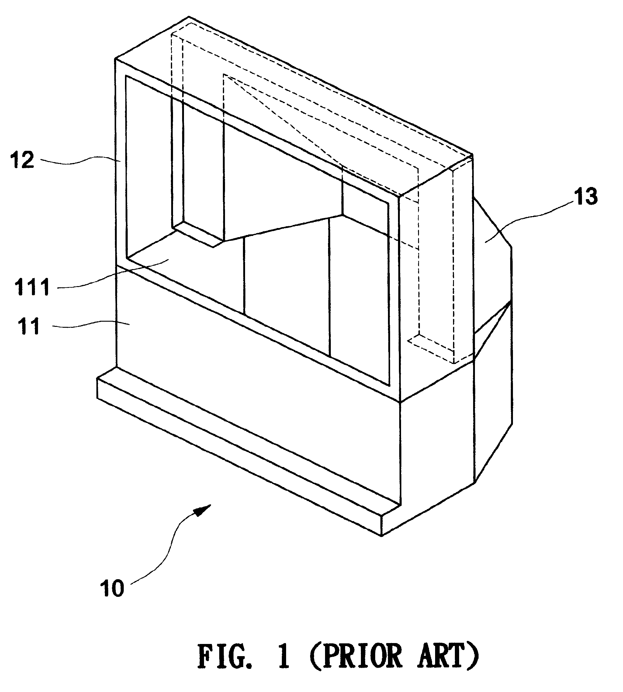
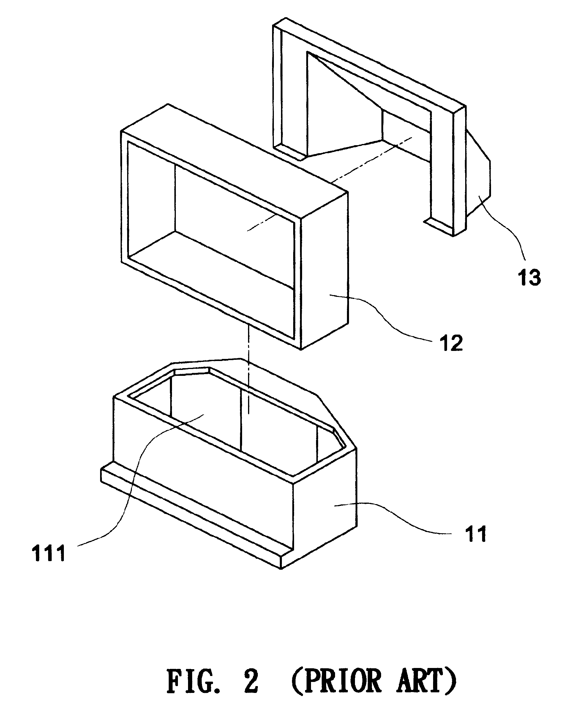
BACKGROUND OF INVENTION[0001]1. Field of the Invention[0002]The invention relates to a projection TV, and more particularly to a projection TV that is convenient to repair.[0003]2. Description of the Prior Art[0004]Referring to FIG. 1, a conventional rear projection television includes a base 11, a front frame 12 and a rear cover 13. The base 11 has an opening 111 at its top portion. Referring to FIG. 2, main components of the rear projection television such as a light engine, a circuit board, a power supply (not shown) are mounted in a basket 11 via an opening 111. The front frame 12 and a screen (not shown) are assembled onto the basket 11. A reflector is mounted at an inner side of the rear cover 13. The front frame 12 is mounted on a front of the rear cover 13 to complete the assembly of the rear projection television.[0005]A conventional rear projection television usually uses a high-power and high-light flux discharge lamp such as metal halide lamp (MHL) and ultra high pressur...

Claims


Application Information

Patent Timeline
IPC IPC(8): H04N5/64H04N5/74
CPCH04N9/3141
Inventor YUAN, YI-CHENGCHEN, CHUN-YAOTSENG, YUNG-CHUANKANG, CHIH-CHUNG
Owner CORETRONIC
Learn More