Anamorphic three-perforation imaging system

an imaging system and three-perforation technology, applied in the field of optimization of image quality, can solve problems such as not maximizing overall image quality, and achieve the effects of reducing magnification and image degradation, reducing the amount of anamorphic squeeze, and reducing image degradation

Active Publication Date: 2006-12-12
PANAVISION INT LP +1
View PDF7 Cites 11 Cited by
  • Summary
  • Abstract
  • Description
  • Claims
  • Application Information

AI Technical Summary

Benefits of technology

[0021]An anamorphic imaging system according to embodiments of the present invention utilizes a maximized image capture area in either cine or digital applications to reduce magnification and image degradation due to magnification when displayed, and to reduce the amount of anamorphic squeeze during photography to lower image degradation due to anamorphosis. The amount of anamorphic squeeze used during photography is, for example, in the ratio of 2.40:1 over 16:9 or approximately 1.34 to maximize the image capture area. Note than an anamorphic squeeze other than this ratio will not maximize the image capture area and thus will not maximize overall image quality.
[0022]In film applications, the present invention utilizes a film frame that is only three perforations in height to reduce the amount of original film needed. The total available frame area in a three perforation high film frame is approximately 0.980 inches by 0.546 inches. Embodiments of the present invention capture images in a frame with an aspect ratio of 16:9, contained within the total available frame area and sized to maximize image area. The image is captured using an anamorphic lens with a horizontal squeeze ratio of approximately 1.34, chosen to horizontally squeeze an image down to the size of the frame while maximizing the image capture area.
[0023]Additionally, the frame may be sized in consideration of digital imagers used for cine applications. Digital imagers may be employed for capturing images for both digital television and motion pictures. Because of the international adoption of 16:9 (1.78:1) as a digital television aspect ratio, digital imaging systems for television and electronic cinematography are being designed to have an aspect ratio of 16:9. In addition, digital imagers for electronic cinematography applications are being designed with a size that approximates the area of three-perforation film as described above. As with film, embodiments of the present invention seek to maximize the active area of a digital imager by capturing the image using an anamorphic lens with a horizontal squeeze of approximately 1.34.
[0024]Preferred embodiments of the present invention therefore employ an image capture area with dimensions selected in consideration of multiple factors, some applicable to both film and digital applications, and some specific to either film or digital applications. The image capture area is selected to maximize the image area to reduce magnification and image degradation due to magnification, and reduce the amount of anamorphic squeeze during filming to lower image degradation due to anamorphosis. Use of a single image capture area also enables the same anamorphic lenses to be used for both film and digital capture. The image capture area is further selected to be only three perforations in height to reduce the amount of original film needed for film applications, and to fit within the maximum three perforation high image area of approximately 0.980 inches by 0.546 inches. The image capture area is still further selected to have an aspect ratio of 16:9 for digital television, and to fit within the total imaging area of a digital imager of approximately 0.945 inches by 0.532 inches.
[0026]For both film and digital applications, the image may be captured using the same anamorphic lens having an approximate 1.34:1 horizontal squeeze, which is less than the 2:1 horizontal squeeze of the Panavision® anamorphic format. The reduced degree of anamorphosis combined with using practically the entire area of the three perforation film frame or total digital imaging area results in a screen image quality that is at least equivalent, and potentially superior to, the Panavision® anamorphic format, while still providing an approximate 25% film cost savings over the conventional four perforation format.
[0027]Embodiments of the present invention utilize known digital processing techniques to convert the original negative film or captured digital image to the format of FIG. 1, which avoids the additional degradation that would occur with the use of optical printer lens.

Problems solved by technology

Note than an anamorphic squeeze other than this ratio will not maximize the image capture area and thus will not maximize overall image quality.

Method used


Image

  • Anamorphic three-perforation imaging system
  • Anamorphic three-perforation imaging system
  • Anamorphic three-perforation imaging system

Examples


Embodiment Construction

[0035]In the following description of preferred embodiments, reference is made to the accompanying drawings that form a part hereof, and in which is shown by way of illustration specific embodiments in which the invention may be practiced. It is to be understood that other embodiments may be utilized and structural changes may be made without departing from the scope of the preferred embodiments of the present invention.

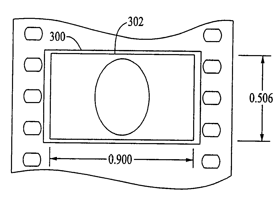
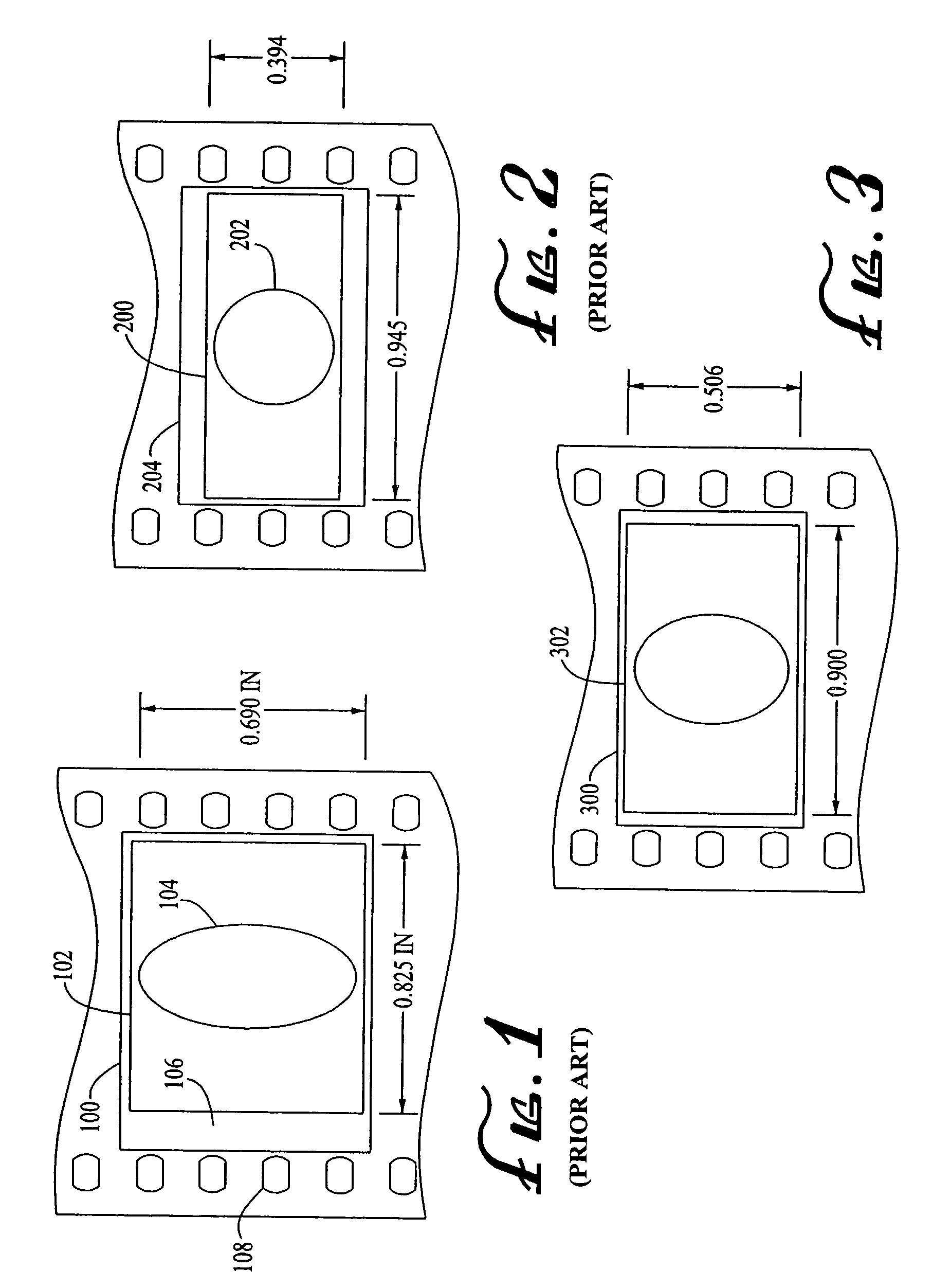
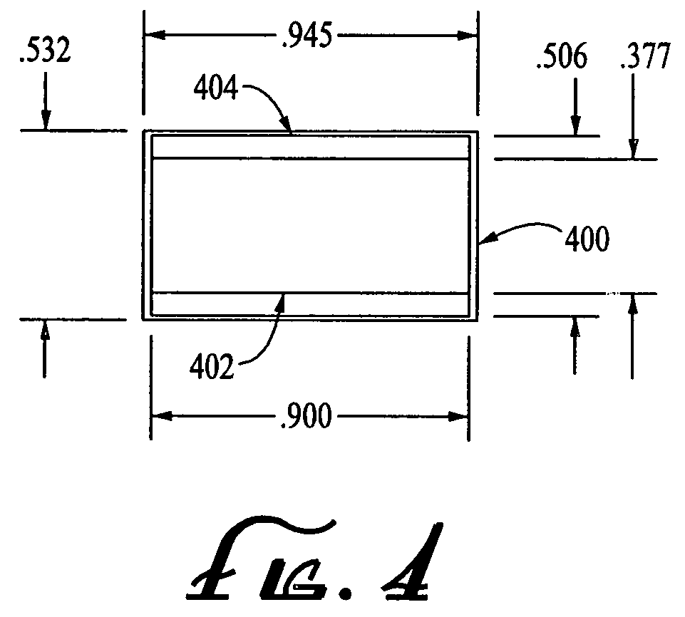
[0036]Embodiments of the present invention utilize a maximized 16:9 aspect ratio image capture area to lower display magnification and image degradation due to display magnification, and to reduce the amount of anamorphic squeeze during photography to lower image degradation due to anamorphosis. The amount of anamorphic squeeze used during filming is in the ratio of 2.40:1 over 16:9 (the ratio of the display aspect ratio over the image capture aspect ratio or approximately 1.34) to maximize the image capture area. Note than an anamorphic squeeze other than the ratio ...


PUM

PropertyMeasurementUnit
aspect ratioaaaaaaaaaa

Abstract

An anamorphic imaging system is disclosed which maximizes the use of available image area to minimize display magnification and image degradation due to display magnification, reduces the amount of anamorphic squeeze during photography to lower image degradation due to anamorphosis, and in film applications, utilizes a film frame that is only three perforations in height to reduce the amount of original film needed. The frame for either film or digital applications has an aspect ratio of approximately 16:9, is contained within the total available frame area of a three-perforation frame or digital imager, and is sized to maximize image area. In preferred embodiments, the image capture area is approximately 0.900 inches wide by approximately 0.506 inches tall.

Description

CROSS-REFERENCE TO RELATED APPLICATIONS[0001]This application claims priority to U.S. Provisional Application No. 60 / 560,800 filed on Apr. 7, 2004, entitled “Anamorphic Three-Perforation Imaging System,” and is related to U.S. Utility application Ser. No. 10 / 923,289 filed on Aug. 20, 2004, entitled “Anamorphic Imaging System,” the contents of which are incorporated by reference herein.BACKGROUND OF THE INVENTION[0002]1. Field of the Invention[0003]The present invention relates, generally, to the optimization of image quality when the aspect ratio of the acquisition format is a generally recognized standard and the display aspect ratio is represented by a different but also generally recognized standard.[0004]2. Description of Related Art[0005]In the early 1950s, as a result of the perceived threat of television, motion pictures began to be released in various widescreen formats. Until this time the majority of feature films and television programs were released with frames having an...

Claims


Application Information

Patent Timeline
Patent Type & Authority Patents(United States)
IPC IPC(8): G03B19/18G02B13/08G03B31/02G11B7/003
CPCG03B31/02G03B37/06G11B7/0032
Inventor MIYAGISHIMA, TAKUOGALT, JOHN JAMES
Owner PANAVISION INT LP
Why Eureka
Try Eureka