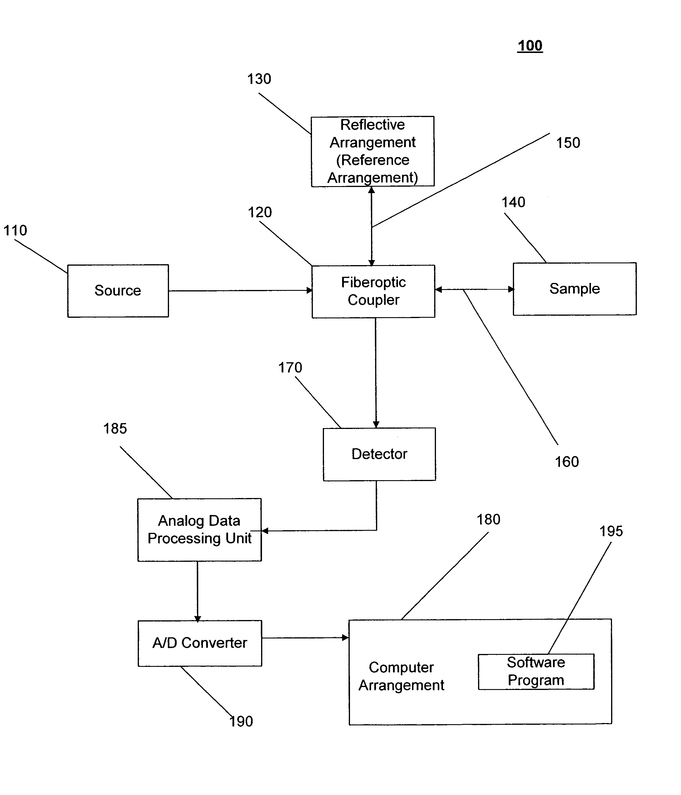
[0007]One of the advantages of the present invention is that OCT signals can be processed to modify the spectral shape of a source having a non-Gaussian spectrum, such that the side lobes in the coherence envelope are reduced or eliminated. Another advantage of the present invention is that the OCT signals can be processed to compensate for the dispersion between the light which is transmitted to the reference arrangement and the light which is transmitted to the sample. Yet another advantage of the present invention is that the OCT signals can be processed to implement a demodulation algorithm for extracting intensity, polarization and / or Doppler shift information from the OCT signals.
[0008]These and other advantages can be achieved with the system and method according to exemplary embodiments of the present invention. With this system and method for imaging the sample, a first combination of light and a second combination of light are received (e.g., by a detector), in which a first cross-correlation function is associated with the first combination and a second cross correlation function is associated with the second combination. Each of the first and the second combinations include a first portion of light which is received from a reference arrangement (e.g., a reflective arrangement, such as a mirror) and a second portion of light which is received from the sample (e.g., a microstructure in biological structure, such as tissue in a human). Moreover, a first relative position of the sample associated with the first combination is different than a second relative position of the sample associated with the second combination.
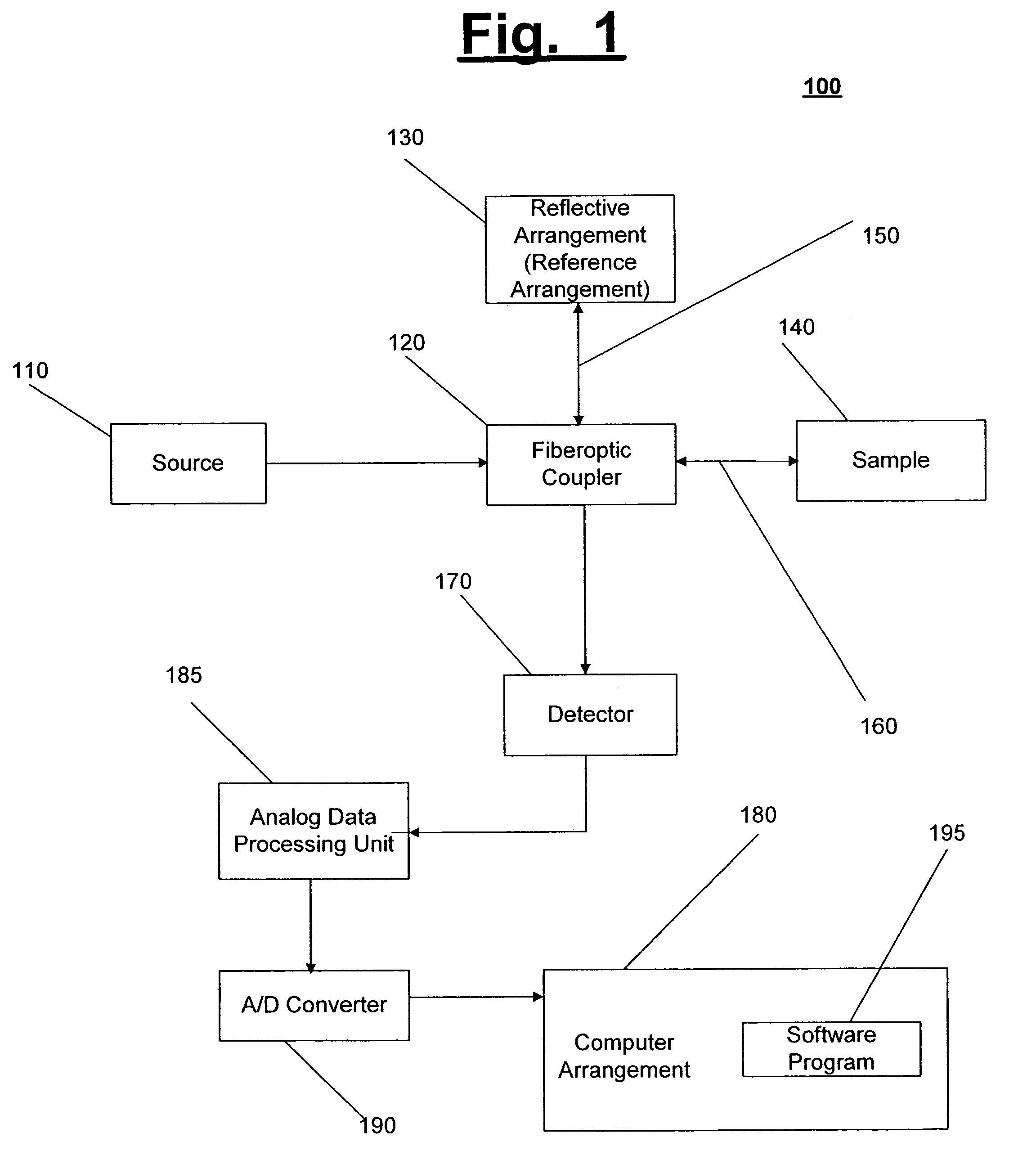
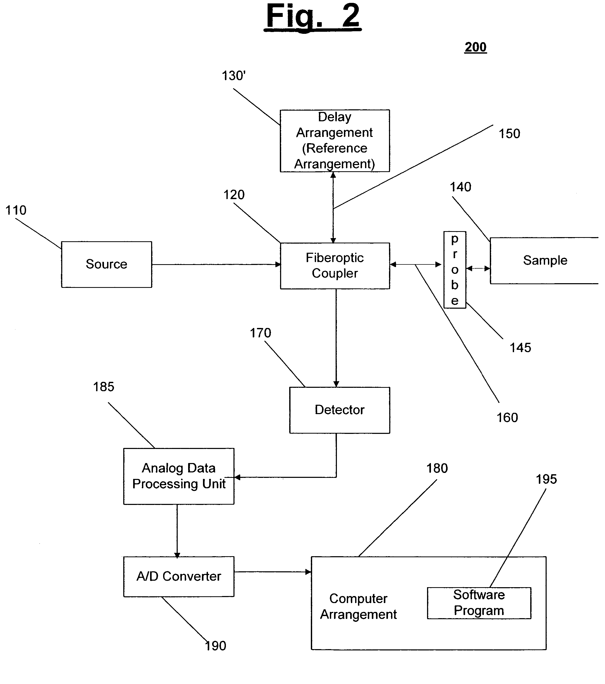
[0009]For example, the first combination of light (e.g., first beam of light) can be transmitted from a source to a fiberoptic coupler (e.g., a beam splitter), and the fiberoptic coupler can divide the first combination of light into the first portion of light and the second portion of light. The first portion of the first combination can be transmitted to the reference arrangement, and the second portion of the first combination can be transmitted to the sample. Also, the first portion of the first combination may reflect off of the reference arrangement and return to the fiberoptic coupler, and the second portion of the first combination may reflect off of the sample and return to the fiberoptic coupler, such that the first portion of the first combination and the second portion of the first combination are recombined at the fiberoptic coupler. In particular, during the transmission of the first combination, a distance between the fiberoptic coupler and the reference arrangement can be altered (e.g., by about 2 mm). The first combination is then transmitted to a detector, and a computer arrangement coupled to the detector may receive a signal or signals associated with the first combination.
[0010]After the computer arrangement receives the signal associated with the first combination, a position of the source and / or a position of the sample can be altered (i.e., the relative position of the sample can be altered), and the second combination of light (e.g., second beam of light) can be transmitted from the source to the fiberoptic coupler. For example, the source and / or the sample can be moved in the X, Y, and / or Z direction. The fiberoptic coupler can divide the second combination of light into the first portion of light and the second portion of light. Further, the first portion of the second combination can be transmitted to the reference arrangement, and the second portion of the second combination can be transmitted to the sample. Also, the first portion of the second combination may reflect off of the reference arrangement and return to the fiberoptic coupler, and the second portion of the second combination may reflect off of the sample and return to the fiberoptic coupler, such that the first portion of the second combination and the second portion of the second combination are recombined at the fiberoptic coupler. In particular, during the transmission of the second combination, the distance between the fiberoptic coupler and the reference arrangement can be altered (e.g., by about 2 mm). For example, the distance between the fiberoptic coupler and the reference arrangement can be altered in the same manner as during the transmission of the first combination. The second combination is then transmitted to the detector, and the computer arrangement may receive a signal or signals associated with the second combination. This may continue for a predetermined number of combinations of light (e.g., any number of combinations of light greater than one combination which are sufficient to image the sample).
[0011]In another exemplary embodiment of the present invention, to modify the spectral shape of the source (i.e., a source having a non-Gaussian spectrum), the first cross correlation function can be transformed (e.g., using a Fourier transform) into a first complex cross spectral density, and the second cross correlation function can be transformed (e.g., using a Fourier transform) into a second complex cross spectral density. Moreover, a third complex cross spectral density can be determined which is approximately an average of the first complex cross spectral density and the second complex cross spectral density, and a particular (e.g., desired) width of a Gaussian spectra of the source can be determined based on the third complex cross spectral density. For example, an area, average amplitude, and width of the third complex cross spectral density can be determined, and the particular width can be determined based on the area, the average amplitude, and the width of the third complex cross spectral density.
[0012]In addition, a correction curve can be determined based on a ratio between the Gaussian spectra and the third complex cross spectral density, and the first complex cross spectral density and the second complex cross spectral density can be modified as a function of the correction curve. For example, the first complex cross spectral density can be multiplied by the correction curve in order to obtain a first modified complex cross spectral density, and the second complex cross spectral density can be multiplied by the correction curve in order to obtain a second modified complex cross spectral density. The first modified complex cross spectral density can then be transformed (e.g., using an inverse Fourier transform) into a first modified cross correlation function, and the second modified complex cross spectral density can be transformed (e.g., using an inverse Fourier transform) into a second modified cross correlation function. Moreover, a coherence function envelope of the sample can be determined based on the first modified cross correlation function and the second modified cross correlation function.